Nissan Juke Service and Repair Manual : Diagnosis and repair workflow
Work Flow
OVERALL SEQUENCE
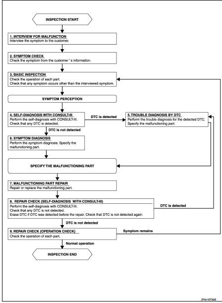
DETAILED FLOW
1.INTERVIEW FOR MALFUNCTION
Interview the symptom to the customer.
>> GO TO 2.
2.SYMPTOM CHECK
Check the symptom from the customer's information.
>> GO TO 3.
3.BASIC INSPECTION
Check the operation of each part. Check that any symptom occurs other than the interviewed symptom.
>> GO TO 4.
4.SELF-DIAGNOSIS WITH CONSULT-III
Perform the self-diagnosis with CONSULT-III. Check that any DTC is detected.
Is any DTC detected? YES >> GO TO 5.
NO >> GO TO 6.
5.TROUBLE DIAGNOSIS BY DTC
Perform the trouble diagnosis for the detected DTC. Specify the malfunctioning part.
>> GO TO 6.
6.SYMPTOM DIAGNOSIS
Perform the symptom diagnosis. Specify the malfunctioning part.
>> GO TO 7.
7.MALFUNCTION PART REPAIR
Repair or replace the malfunctioning part.
>> GO TO 8.
8.REPAIR CHECK (SELF-DIAGNOSIS WITH CONSULT-III)
Perform the self-diagnoses with CONSULT-III. Check that any DTC is not detected. Erase DTC if DTC is detected before the repair. Check that DTC is not detected again.
Is any or malfunction result or DTC detected? YES >> If DTC is detected, GO TO 5.
NO >> GO TO 9.
9.REPAIR CHECK (OPERATION CHECK)
Check the operation of each part.
Does it operate normally? YES >> INSPECTION END
NO >> GO TO 3
 Basic inspection
...
 Operation inspection
Work Procedure
The purpose of the operational check is to check that the individual system
operates normally.
Check condition : Engine running at normal operating temperature.
1.CHECK BLOWER MOTO ...
Other materials:
Installing front license plate
Use the following steps to mount the license plate:
Before mounting the license plate, confirm that the following parts are enclosed
in the plastic bag.
• License plate bracket
• J-nut 2
• Screw 2
• Screw grommet 2
1. Park the vehicle on flat, ...
Cooling fan
Exploded View
1. Fan motorCooling fan
2. Fan shroud
3. Cooling fan
A. Reverse screw
: Apply thread locking sealant.
: Vehicle front
: N·m (kg-m, in-lb)
Removal and Installation
REMOVAL
1. Drain engine coolant. Refer to CO-62, "Draining".
2. Disconnect radiator hose (lower) ...
Tire equipment
SUMMER tires have a tread designed to provide superior performance on dry pavement.
However, the performance of these tires will be substantially reduced in snowy and
icy conditions.
If you operate your vehicle on snowy or icy roads, NISSAN recommends the use
of MUD & SNOW or ALL SEASON t ...
