Nissan Juke Service and Repair Manual : Daytime running light relay circuit
Component Function Check
1.CHECK DAYTIME RUNNING LIGHT OPERATION
 CONSULT-III ACTIVE TEST
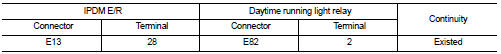
1. Select “EXTERNAL LAMPS” of IPDM E/R active test item.
2. With operating the test item, check that parking lamp, tail lamp and license plate lamp are turned ON.
TAIL : Parking lamp, tail lamp and license plate lamp ON Off : Parking lamp, tail lamp and license plate lamp OFF
Is the inspection result normal? YES >> Daytime running light relay circuit is normal.
NO >> Refer to EXL-50, "Diagnosis Procedure".
Diagnosis Procedure
1.CHECK DAYTIME RUNNING LIGHT RELAY FUSE
1. Turn ignition switch OFF.
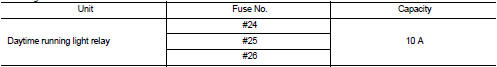
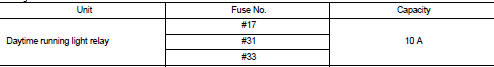
2. Check that the following fuse is not fusing.
Gasoline engine models
Diesel engine models
Is the inspection result normal? YES >> GO TO 2.
NO >> Replace the fuse after repairing the applicable circuit.
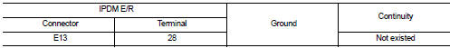
2.CHECK DAYTIME RUNNING LIGHT RELAY POWER SUPPLY
1. Remove daytime running light relay.
2. Check voltage between daytime running light relay harness connector and ground.
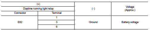
Is the inspection result normal? YES >> GO TO 3.
NO >> Repair or replace harness.
3.CHECK DAYTIME RUNNING LIGHT RELAY
Check daytime running light relay. Refer to EXL-51, "Component Inspection".
Is the inspection result normal? YES >> GO TO 4.
NO >> Replace daytime running light relay.
4.CHECK DAYTIME RUNNING LIGHT RELAY CONTROL SIGNAL OUTPUT
 CONSULT-III ACTIVE TEST
1. Install daytime running light relay.
2. Turn ignition switch ON.
3. Select “EXTERNAL LAMPS” of IPDM E/R active test item.
4. With operating the test item, check voltage between IPDM E/R harness connector and ground.
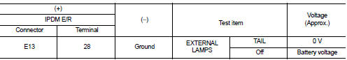
Is the inspection result normal? YES >> Daytime running light relay circuit is OK.
Fixed at 0 V >>GO TO 5.
Fixed at battery voltage >>Replace IPDM E/R.
5.CHECK DAYTIME RUNNING LIGHT RELAY CONTROL SIGNAL OPEN CIRCUIT
1. Turn ignition switch OFF.
2. Remove daytime running light relay.
3. Disconnect IPDM E/R harness connector.
4. Check continuity between IPDM E/R harness connector and daytime running light relay harness connector.
Is the inspection result normal? YES >> GO TO 6.
NO >> Repair or replace harness.
6.CHECK DAYTIME RUNNING LIGHT RELAY CONTROL SIGNAL SHORT CIRCUIT
Check continuity between IPDM E/R harness connector and ground.
Is the inspection result normal? YES >> Replace IPDM E/R.
NO >> Repair or replace harness.
Component Inspection
1.CHECK DAYTIME RUNNING LIGHT RELAY
1. Turn ignition switch OFF.
2. Remove daytime running light relay.
3. Apply battery voltage to daytime running light relay between terminals 1 and 2.
4. Check continuity of daytime running light relay.
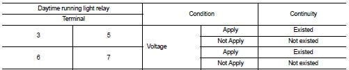
Is the inspection result normal? YES >> Daytime running light relay is normal.
NO >> Replace daytime running light relay.
 Headlamp ground circuit
Diagnosis Procedure
1.CHECK HEADLAMP GROUND OPEN CIRCUIT
1. Turn ignition switch OFF.
2. Disconnect headlamp connector.
3. Check continuity between headlamp harness connector and ground.
Is the ...
 Headlamp aiming system (manual)
Component Inspection
1.CHECK HEADLAMP AIMING SWITCH
1. Remove headlamp aiming switch.
2. Check resistance among each headlamp aiming switch terminal.
Is the inspection result normal?
YES >&g ...
Other materials:
Symptom diagnosis
Noise, vibration and harshnesS (NVH) Troubleshooting
NVH Troubleshooting - Engine Noise
Use the Chart Below to Help You Find the Cause
of the Symptom
1. Locate the area where noise occurs.
2. Confirm the type of noise.
3. Specify the operating condition of engine.
4. Check specified noise s ...
Vehicle loading information
WARNING
It is extremely dangerous to ride in the cargo area inside the vehicle.
In the event of a collision, individuals positioned in these unsecured areas are significantly more likely to suffer serious injury or fatalities.
Never allow passengers to ...
Telematics overview (models with Navigation System)
In addition to the Event Data Recorders (EDRs) detailed elsewhere in this Owner's Manual, your Nissan Leaf is equipped with advanced electronic modules. These systems continuously monitor, control, and record data concerning various vehicle operations, including the electric motor, battery health, b ...
