Nissan Juke Service and Repair Manual : B27A6, B27A7, B27A8, B27A9 mode door motor
DTC Logic
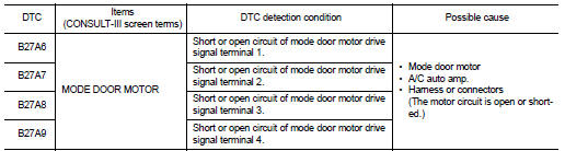
DTC DETECTION LOGIC
NOTE
:
ŌĆó If DTC is displayed along with DTC U1000, first perform the trouble diagnosis
for DTC U1000. Refer to HAC-
51, "DTC Logic".
ŌĆó If DTC is displayed along with DTC U1010, first perform the trouble diagnosis for DTC U1010. HAC-52, "DTC Logic".
ŌĆó If mode door motors DTC (B27A6 ŌĆō B27A9) are detected, there is probably a disconnected connector or an open circuit in mode door motor drive power supply harness.
DTC CONFIRMATION PROCEDURE
1.PERFORM DTC CONFIRMATION PROCEDURE
 With CONSULT-III
1. Turn ignition switch ON.
2. Select ŌĆ£Self Diagnostic ResultŌĆØ mode of ŌĆ£HVACŌĆØ using CONSULT-III.
3. Check DTC.
Is DTC detected? YES >> Refer to HAC-71, "Diagnosis Procedure".
NO >> INSPECTION END
Diagnosis Procedure
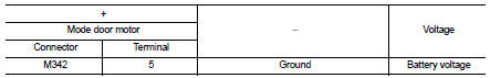
1.CHECK MODE DOOR MOTOR POWER SUPPLY
1. Turn ignition switch OFF.
2. Disconnect mode door motor connector.
3. Turn ignition switch ON.
4. Check voltage between mode door motor harness connector and ground.
Is the inspection result normal? YES >> GO TO 2.
NO >> Repair harness or connector between mode door motor and fuse.
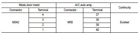
2.CHECK MODE DOOR MOTOR DRIVE SIGNAL CIRCUIT FOR OPEN
1. Turn ignition switch OFF.
2. Disconnect A/C auto amp. connector.
3. Check continuity between mode door motor harness connector and A/C auto amp. harness connector.
Is the inspection result normal? YES >> GO TO 3.
NO >> Repair harness or connector.
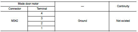
3.CHECK MODE DOOR MOTOR DRIVE SIGNAL CIRCUIT FOR SHORT
Check continuity between mode door motor harness connector and A/C auto amp. harness connector.
Is the inspection result normal? YES >> GO TO 4.
NO >> Repair harness or connector.
4.CHECK MODE DOOR MOTOR
Check mode door motor. Refer to HAC-72, "Component Inspection".
Is the inspection result normal? YES >> Replace A/C auto amp. Refer to HAC-91, "Removal and Installation".
NO >> Replace mode door motor. Refer to HAC-100, "MODE DOOR MOTOR : Removal and Installation".
Component Inspection
1.CHECK MODE DOOR MOTOR
1. Remove mode door motor. Refer to HAC-100, "MODE DOOR MOTOR : Removal and Installation".
2. Check resistance between mode door motor terminals. Refer to applicable table for the normal value.
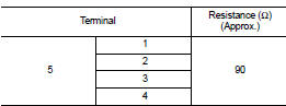
Is the inspection result normal? YES >> INSPECTION END
NO >> Replace mode door motor. Refer to HAC-100, "MODE DOOR MOTOR : Removal and Installation".
 B27A2, B27A3, B27A4, B27A5 air mix door motor
DTC Logic
DTC DETECTION LOGIC
NOTE:
ŌĆó If DTC is displayed along with DTC U1000, first perform the trouble diagnosis
for DTC U1000. Refer to HAC-
51, "DTC Logic".
ŌĆó If DTC is displ ...
 Power supply and ground circuit
A/C auto AMP. : Diagnosis Procedure
1.CHECK SYMPTOM
Check symptom (A or B).
Which symptom is detected?
A >> GO TO 2.
B >> GO TO 5.
2.CHECK FUSE
1. Turn ignition switch OFF.
2 ...
Other materials:
General maintenance
General Maintenance
General maintenance includes those items which should be checked during the
normal day-to-day operation
of the vehicle. They are essential if the vehicle is to continue operating
properly. The owners can perform
checks and inspections themselves or they can have their NISS ...
System
Can communication system
CAN COMMUNICATION SYSTEM : System Diagram
CAN COMMUNICATION SYSTEM : System Description
Description
ŌĆó CAN (Controller Area Network) is a serial communication line for real time
application. It is an on-vehicle
multiplex communication line with high data communicat ...
C1601 battery power supply
DTC Logic
DTC DETECTION LOGIC
DTC CONFIRMATION PROCEDURE
1.PRECONDITIONING
If ŌĆ£DTC CONFIRMATION PROCEDUREŌĆØ has been previously conducted, always turn
ignition switch OFF and
wait at least 10 seconds before conducting the next test.
>> GO TO 2.
2.DTC REPRODUCTION PROCEDURE
W ...
