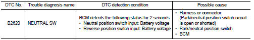
Nissan Juke Service and Repair Manual : B2620 Park/neutral position switch
DTC Logic
DTC DETECTION LOGIC
DTC CONFIRMATION PROCEDURE
1.PERFORM DTC CONFIRMATION PROCEDURE
1. Turn ignition switch ON and wait 2 seconds or more under the following conditions.
2. Set shift lever in the Neutral position and wait for 2 seconds or more.
3. Set shift lever in the Reverse position and wait for 2 seconds or more.
4. Check DTC in “Self Diagnostic Result” mode of “BCM” using CONSULT-III.
Is DTC detected? YES >> Go to SEC-110, "Diagnosis Procedure".
NO >> INSPECTION END
Diagnosis Procedure
1.CHECK PARK/NEUTRAL POSITION SWITCH POWER SUPPLY
1. Turn ignition switch OFF.
2. Disconnect park/neutral position switch connector.
3. Turn ignition switch ON.
4. Check voltage between park/neutral position switch harness connector and ground.
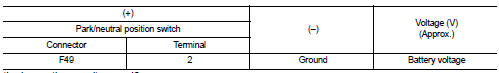
Is the inspection result normal? YES >> GO TO 2.
NO-1 >> Check 10 A fuse [No. 5, located in the fuse block (J/B)].
NO-2 >> Check harness for open or short between park/neutral position switch and fuse.
2.CHECK NEUTRAL POSITION SWITCH SIGNAL
1. Turn ignition switch OFF.
2. Connect park/neutral position switch connector.
3. Turn ignition switch ON.
4. Check voltage between BCM harness connector and ground
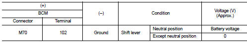
Is the inspection result normal? YES >> GO TO 4.
NO >> GO TO 3.
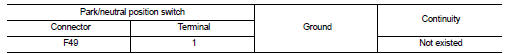
3.CHECK NEUTRAL POSITION SWITCH SIGNAL CIRCUIT
1. Turn ignition switch OFF.
2. Disconnect park/neutral position switch connector.
3. Disconnect BCM connector.
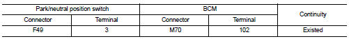
4. Check continuity between park/neutral position switch harness connector and BCM harness connector.
5. Check continuity between park/neutral position switch harness connector and ground.
Is the inspection result normal? YES >> GO TO 6.
NO >> Repair or replace harness.
4.CHECK REVERSE POSITION SWITCH SIGNAL
Check voltage between BCM harness connector and ground.
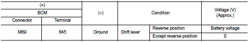
Is the inspection result normal? YES >> GO TO 8.
NO >> GO TO 5.
5.CHECK REVERSE POSITION SWITCH SIGNAL CIRCUIT
1. Turn ignition switch OFF.
2. Disconnect park/neutral position switch connector.
3. Disconnect BCM connector.
4. Check continuity between park/neutral position switch harness connector and BCM harness connector.
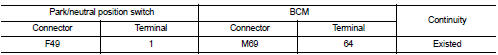
5. Check continuity between park/neutral position switch harness connector and ground.
Is the inspection result normal? YES >> GO TO 6.
NO >> Repair or replace harness.
6.CHECK PARK/NEUTRAL POSITION SWITCH
Refer to SEC-112, "Component Inspection".
Is the inspection result normal? YES >> GO TO 7.
NO >> Replace park/neutral position switch. Refer to TM-24, "Removal and Installation". (5MT: RS5F92R) or TM-77, "Removal and Installation" (6MT: RS6F94R).
7.CHECK INTERMITTENT INCIDENT
Refer to GI-42, "Intermittent Incident".
>> INSPECTION END
8.REPLACE BCM
1. Replace BCM. Refer to BCS-93, "Removal and Installation".
2. Perform initialization of BCM and reregistration of all Intelligent Key using CONSULT-III.
For initialization and reregistration procedures, refer to CONSULT-III Operation Manual NATS-IVIS/NVIS.
>> INSPECTION END
Component Inspection
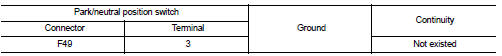
1.CHECK PARK/NEUTRAL POSITION SWITCH
1. Turn ignition switch OFF.
2. Disconnect park/neutral position switch connector.
3. Check continuity between park/neutral position switch terminals under the following conditions.
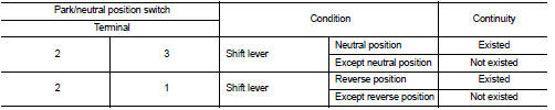
Is the inspection result normal? YES >> INSPECTION END
NO >> Replace park/neutral position switch. Refer to TM-24, "Removal and Installation". (5MT: RS5F92R) or TM-77, "Removal and Installation" (6MT: RS6F94R).
 B261F ASCD clutch switch
DTC Logic
DTC DETECTION LOGIC
NOTE:
• If DTC B261F is displayed with DTC U1000, first perform the trouble diagnosis
for DTC U1000. Refer to
BCS-83, "DTC Logic".
• If DTC B261F is ...
 B26E8 clutch interlock switch
DTC Logic
NOTE:
• If DTC B26E8 is displayed with DTC B210F, first perform the trouble diagnosis
for DTC B210F. Refer to
BCS-83, "DTC Logic".
• If DTC B26E8 is displayed with DTC B2 ...
Other materials:
Front wheel hub and knuckle
Exploded View
1. Steering knuckle
2. Splash guard
3. Hub bolt
4. Wheel hub assembly (Bearing-integrated
type)
5. Disc rotor
6. Wheel hub lock nut
7. Adjusting cap
8. Cotter pin
A. Tightening must be done following the installation procedure. Refer to
FAX-43, "Removal and Insta ...
Precaution
Precaution for Supplemental Restraint System (SRS) "AIR BAG" and "SEAT
BELT
PRE-TENSIONER"
The Supplemental Restraint System such as “AIR BAG” and “SEAT BELT PRE-TENSIONER”,
used along
with a front seat belt, helps to reduce the risk or severity of injury to the
...
Steering Assist limitations
WARNING
In the following situations, the front-facing camera may fail to identify lane markers accurately or misinterpret road features, which may result in the Steering Assist system failing to operate as intended:
When navigating roads with confusing, ...
