
Nissan Juke Service and Repair Manual : B209f cranking request circuit
DTC Logic
DTC DETECTION LOGIC
NOTE
:
If DTC B209F is displayed with DTC U1000, first perform the trouble diagnosis
for DTC U1000. Refer to PCS-
59, "DTC Logic".
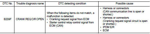
DTC CONFIRMATION PROCEDURE
1.PERFORM DTC CONFIRMATION PROCEDURE
1. Perform DTC CONFIRMATION PROCEDURE for DTC P1650. Refer to EC-366, "DTC Logic" (MR16DDT) or EC-725, "DTC Logic" (HR16DE).
2. Turn ignition switch ON.
3. Check DTC in “Self Diagnostic Result� mode of “IPDM E/R� using CONSULT-III.
Is DTC detected? YES >> Refer to SEC-209, "Diagnosis Procedure".
NO >> INSPECTION END
Diagnosis Procedure
1.CHECK CRANKING REQUEST SIGNAL
1. Turn ignition switch ON.
2. Check voltage between IPDM E/R harness connector and ground under the following conditions.
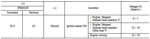
Is the inspection result normal? YES >> GO TO 3.
NO >> GO TO 2.
2.CHECK CRANKING REQUEST SIGNAL CIRCUIT
1. Turn ignition switch OFF.
2. Disconnect IPDM E/R connector.
3. Disconnect ECM connector.
4. Check continuity between IPDM E/R harness connector and ECM harness connector.

5. Check continuity between BCM harness connector and ground.

Is the inspection result normal? YES >> GO TO 3.
NO >> Repair or replace harness.
3.REPLACE IPDM E/R
1. Replace IPDM E/R. Refer to PCS-63, "Removal and Installation".
2. Perform DTC CONFIRMATION PROCEDURE for DTC B209F. Refer to SEC-209, "DTC Logic".
Is DTC detected? YES >> GO TO 4.
NO >> INSPECTION END
4.REPLACE ECM
Replace ECM.
Refer to EC-447, "Removal and Installation" (MR16DDT) or EC-805, "Removal and Installation" (HR16DE).
>> INSPECTION END
 B2196 dongle unit
Description
BCM performs ID verification between BCM and dongle unit.
When verification result is OK, BCM permits cranking.
DTC Logic
DTC DETECTION LOGIC
DTC CONFIRMATION PROCEDURE
1.PERFORM ...
 B20A0 cranking request circuit
DTC Logic
DTC DETECTION LOGIC
NOTE:
If DTC B20A0 is displayed with DTC U1000, first perform the trouble diagnosis
for DTC U1000. Refer to PCS-
59, "DTC Logic".
DTC CONFIRMATION PROC ...
Other materials:
Power supply and ground circuit
AUDIO UNIT
AUDIO UNIT : Diagnosis Procedure
1.CHECK FUSE
Check for blown fuses.
Is inspection result OK?
YES >> GO TO 2.
NO >> Be sure to eliminate cause of malfunction before installing new fuse.
2.CHECK POWER SUPPLY CIRCUIT
Check voltage between audio unit harness connect ...
Audio unit
Removal and Installation
REMOVAL
1. Remove cluster lid C. Refer to IP-12, "Exploded View".
2. Remove audio unit screws.
3. Disconnect audio unit connectors to remove audio unit and brackets as a
single unit.
4. Remove brackets screws to remove audio unit.
INSTALLATION
1. Install ...
B1148 curtain air bag module
DTC Logic
DTC DETECTION LOGIC
DTC CONFIRMATION PROCEDURE
1.CHECK SELF-DIAG RESULT
With CONSULT-III
1. Turn ignition switch ON.
2. Perform “Self Diagnostic Result� mode of “AIR BAG� using CONSULT-III.
Without CONSULT-III
1. Turn ignition switch ON.
2. Check the air bag warning la ...
