Nissan Juke Service and Repair Manual : B1090, B1091, B1092, B1093, B1094, B1095 diagnosis sensor unit
DTC Logic
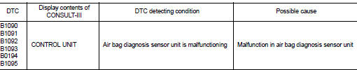
DTC DETECTION LOGIC
DTC CONFIRMATION PROCEDURE
1.CHECK SELF-DIAG RESULT
 With CONSULT-III
1. Turn ignition switch ON.
2. Perform “Self Diagnostic Result” mode of “AIR BAG” using CONSULT-III.
 Without CONSULT-III
1. Turn ignition switch ON.
2. Check the air bag warning lamp status. Refer to SRC-12, "On Board Diagnosis Function".
NOTE
:
SRS does not enter the diagnosis mode if no malfunction is detected in the user
mode.
Is malfunctioning part detected? YES >> Refer to SRC-81, "Diagnosis Procedure".
NO >> INSPECTION END
Diagnosis Procedure
WARNING:
• Before servicing, turn ignition switch OFF, disconnect battery negative terminal, and wait at least 3 minutes or more. (To discharge backup capacitor.) • Never use unspecified tester or other measuring device.
1.CHECK HARNESS CONNECTOR
Check the harness connector.
Is the inspection result normal? YES >> GO TO 2.
NO >> Replace harness connectors.
2.CHECK WIRING HARNESS
Check the wiring harness externals.
Is the inspection result normal? YES >> GO TO 3.
NO >> Replace wiring harness.
3.REPLACE AIR BAG DIAGNOSIS SENSOR UNIT
1. Replace air bag diagnosis sensor unit. Refer to SR-30, "Removal and Installation".
2. Perform DTC confirmation procedure. Refer to SRC-81, "DTC Logic".
Is DTC detected? YES >> GO TO 1.
NO >> INSPECTION END
 B1089 seat belt Pre-tensioner LH
DTC Logic
DTC DETECTION LOGIC
DTC CONFIRMATION PROCEDURE
1.CHECK SELF-DIAG RESULT
With CONSULT-III
1. Turn ignition switch ON.
2. Perform “Self Diagnostic Result” mode of “AIR BAG” usi ...
 B1106, B1107, B1108, B1109, B1110, B1111 diagnosis sensor unit
DTC Logic
DTC DETECTION LOGIC
DTC CONFIRMATION PROCEDURE
1.CHECK SELF-DIAG RESULT
With CONSULT-III
1. Turn ignition switch ON.
2. Perform “Self Diagnostic Result” mode of “AIR BAG” usi ...
Other materials:
System temporarily unavailable
When the system detects that the radar sensors are blocked, it will automatically deactivate to prevent inaccurate warnings. During this state, the BSW indicator (1) will blink in yellow on your vehicle information display, and the indicator adjacent to "Blind spot" within the ...
Rear-facing child restraint installation using LATCH
Refer to all Warnings and Cautions in the “Child safety” and “Child restraints”
sections before installing a child restraint.
Follow these steps to install a rear-facing child restraint using the LATCH system:
1. Position the child restraint on the seat.
Always follow the child restrain ...
Fuel injector and fuel tube
Exploded View
1. Holder
2. Seal ring (white)
3. Backup ring
4. O-ring (blue)
5. Fuel injector
6. Stud bolt
7. Fuel tube assembly
8. Fuel tube insulator
9. Fuel tube protector
10. Fuel pressure sensor
11. O-ring
12. Fuel tube adaptor
13. Backup ring (white)
14. Backup ring ( ...
