Nissan Juke Service and Repair Manual : B1106, B1107, B1108, B1109, B1110, B1111 diagnosis sensor unit
DTC Logic
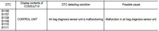
DTC DETECTION LOGIC
DTC CONFIRMATION PROCEDURE
1.CHECK SELF-DIAG RESULT
 With CONSULT-III
1. Turn ignition switch ON.
2. Perform ÔÇťSelf Diagnostic ResultÔÇŁ mode of ÔÇťAIR BAGÔÇŁ using CONSULT-III.
 Without CONSULT-III
1. Turn ignition switch ON.
2. Check the air bag warning lamp status. Refer to SRC-12, "On Board Diagnosis Function".
NOTE
:
SRS does not enter the diagnosis mode if no malfunction is detected in the user
mode.
Is malfunctioning part detected? YES >> Refer to SRC-82, "Diagnosis Procedure".
NO >> INSPECTION END
Diagnosis Procedure
WARNING:
ÔÇó Before servicing, turn ignition switch OFF, disconnect battery negative
terminal, and wait at least 3
minutes or more. (To discharge backup capacitor.)
ÔÇó Never use unspecified tester or other measuring device.
1.CHECK HARNESS CONNECTOR
Check the harness connector.
Is the inspection result normal? YES >> GO TO 2.
NO >> Replace harness connectors.
2.CHECK WIRING HARNESS
Check the wiring harness externals.
Is the inspection result normal? YES >> GO TO 3.
NO >> Replace wiring harness.
3.REPLACE AIR BAG DIAGNOSIS SENSOR UNIT
1. Replace air bag diagnosis sensor unit. Refer to SR-30, "Removal and Installation".
2. Perform DTC confirmation procedure. Refer to SRC-82, "DTC Logic".
Is DTC detected? YES >> GO TO 1.
NO >> INSPECTION END
 B1090, B1091, B1092, B1093, B1094, B1095 diagnosis sensor unit
DTC Logic
DTC DETECTION LOGIC
DTC CONFIRMATION PROCEDURE
1.CHECK SELF-DIAG RESULT
With CONSULT-III
1. Turn ignition switch ON.
2. Perform ÔÇťSelf Diagnostic ResultÔÇŁ mode of ÔÇťAIR BAGÔÇŁ usi ...
 B1113, B1114 satellite sensor RH
DTC Logic
DTC DETECTION LOGIC
1.CHECK SELF-DIAG RESULT
With CONSULT-III
1. Turn ignition switch ON.
2. Perform ÔÇťSelf Diagnostic ResultÔÇŁ mode of ÔÇťAIR BAGÔÇŁ using CONSULT-III.
Without C ...
Other materials:
P1553 battery current sensor
DTC Logic
DTC DETECTION LOGIC
DTC CONFIRMATION PROCEDURE
1.PRECONDITIONING
If DTC Confirmation Procedure has been previously conducted, always perform
the following before conducting
the next test.
1. Turn ignition switch OFF and wait at least 10 seconds.
2. Turn ignition switch ON.
3. ...
P0778 pressure control solenoid B
DTC Logic
DTC DETECTION LOGIC
DTC CONFIRMATION PROCEDURE
NOTE:
If ÔÇťDTC CONFIRMATION PROCEDUREÔÇŁ has been previously performed, always turn
ignition switch
OFF and wait at least 10 seconds before performing the next test.
After the repair, perform the following procedure to confirm the ...
Aluminum alloy wheels
Wash regularly with a sponge dampened in a mild soap solution, especially during
winter months in areas where road salt is used. Salt could discolor the wheels if
not removed.
CAUTION
Follow the directions below to avoid staining or discoloring the wheels:
ÔÇó Do not use a cleaner that uses s ...
