Nissan Juke Service and Repair Manual : A/C control
Exploded View
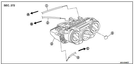
1. Intake door cable
2. Mode door cable
3. A/C control
4. Air mix door cable
5. Intake door lever knob
A. To mode door link
B. To intake door link
C. To air mix door link
Removal and Installation
REMOVAL
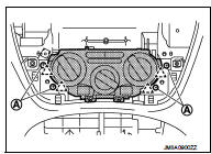
1. Remove A/C finisher. Refer to IP-13, "Removal and Installation".
2. Remove A/C control fixing screws (A) and fixing pawls, and then remove A/C control.
 Pawl
Pawl
3. Disconnect door cable and harness connector from A/C control.
INSTALLATION
Install in the reverse order of removal.

 Thermo control amplifier
Removal and Installation
REMOVAL
1. Remove evaporator. Refer to HA-115, "EVAPORATOR : Removal and
Installation".
2. Remove thermo control amp. from evaporator.
INSTALLATION
Note the ...
Other materials:
Precaution for Supplemental Restraint System (SRS) "AIR BAG" and "SEAT BELT
PRE-TENSIONER"
The Supplemental Restraint System such as ŌĆ£AIR BAGŌĆØ and ŌĆ£SEAT BELT PRE-TENSIONERŌĆØ,
used along
with a front seat belt, helps to reduce the risk or severity of injury to the
driver and front passenger for certain
types of collision. Information necessary to service the system safely is
...
Control linkage
Exploded View
1. Bracket
2. Shifter cable
3. Selector lever
4. Shifter lever A
5. Tapping bolt
6. Cable mounting bracket
7. Selector cable
8. Grommet
9. M/T shift selector assembly
10. Shifter lever
11. Shifter lever knob
: Always replace after every
disassembly.
: N┬Ęm (kg-m ...
Fuel filter
Exploded View
Removal and Installation
REMOVAL (RHD)
1. Remove quick connectors in the following procedures.
ŌĆó Pinch quick connector square-parts with your fingers, and pull
out the quick connector by hand.
ŌĆó If quick connector and tube on vehicle are stuck, push and pull
several ti ...
