Nissan Juke Service and Repair Manual : B2578, B2579 In-vehicle sensor
DTC Logic
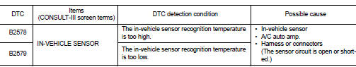
DTC DETECTION LOGIC
NOTE
:
• If DTC is displayed along with DTC U1000, first perform the trouble diagnosis
for DTC U1000. Refer to HAC-
141, "DTC Logic".
• If DTC is displayed along with DTC U1010, first perform the trouble diagnosis for DTC U1010. Refer to HAC- 142, "DTC Logic".
DTC CONFIRMATION PROCEDURE
1.PERFORM DTC CONFIRMATION PROCEDURE
 With CONSULT-III
1. Turn ignition switch ON.
2. Select “Self Diagnostic Result” mode of “HVAC” using CONSULT-III.
3. Check DTC.
Is DTC detected? YES >> Refer to HAC-143, "Diagnosis Procedure".
NO >> INSPECTION END
Diagnosis Procedure
1.CHECK IN-VEHICLE SENSOR POWER SUPPLY
1. Turn ignition switch OFF.
2. Disconnect in-vehicle sensor connector.
3. Turn ignition switch ON.
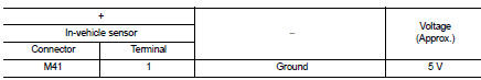
4. Check voltage between in-vehicle sensor harness connector and ground.
Is the inspection result normal? YES >> GO TO 2.
NO >> GO TO 4.
2.CHECK IN-VEHICLE SENSOR GROUND CIRCUIT FOR OPEN
1. Turn ignition switch OFF.
2. Disconnect A/C auto amp. connector.
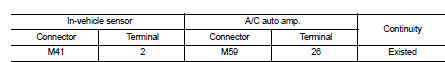
3. Check continuity between in-vehicle sensor harness connector and A/C auto amp harness connector.
Is the inspection result normal?
YES >> GO TO 3.
NO >> Repair harness or connector.
3.CHECK IN-VEHICLE SENSOR
Check in-vehicle sensor. Refer to HAC-147, "Component Inspection".
Is the inspection result normal? YES >> Replace A/C auto amp. Refer to HAC-188, "Removal and Installation".
NO >> Replace in-vehicle sensor. Refer to HAC-190, "Removal and Installation".
4.CHECK IN-VEHICLE SENSOR POWER SUPPLY CIRCUIT FOR OPEN
1. Turn ignition switch OFF.
2. Disconnect A/C auto amp. connector.
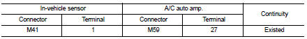
3. Check continuity between in-vehicle sensor harness connector and A/C auto amp. harness connector.
Is the inspection result normal? YES >> GO TO 5.
NO >> Repair harness or connector.
5.CHECK IN-VEHICLE SENSOR POWER SUPPLY CIRCUIT FOR SHORT
Check continuity between in-vehicle sensor harness connector and ground.
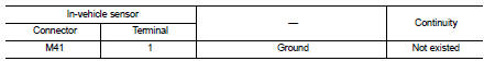
Is the inspection result normal? YES >> Replace A/C auto amp. Refer to HAC-188, "Removal and Installation".
NO >> Repair harness or connector.
Component Inspection
1.CHECK IN-VEHICLE SENSOR
1. Remove in-vehicle sensor. Refer to HAC-190, "Removal and Installation".
2. Check resistance between in-vehicle sensor terminals. Refer to applicable table for the normal value.
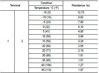
Is the inspection result normal? YES >> INSPECTION END
NO >> Replace in-vehicle sensor. Refer to HAC-190, "Removal and Installation".
 U1010 control unit (can)
Description
Initial diagnosis of A/C auto amp.
DTC Logic
DTC DETECTION LOGIC
DTC CONFIRMATION PROCEDURE
1.PERFORM SELF-DIAGNOSIS
With CONSULT-III
1. Turn ignition switch ON.
2. Select “Sel ...
 B257B, B257C ambient sensor
DTC Logic
DTC DETECTION LOGIC
NOTE:
• If DTC is displayed along with DTC U1000, first perform the trouble diagnosis
for DTC U1000. Refer to HAC-
141, "DTC Logic".
• If DTC is disp ...
Other materials:
Removal and Installation
REMOVAL
1. Remove engine assembly. Refer to EM-55, "2WD : Exploded View" (2WD) ,
EM-59, "4WD : Exploded
View" (4WD).
2. Remove oil pan (lower). Refer to EM-41, "Removal and Installation".
3. Remove front cover, and other related parts. Refer to EM-67, "Explod ...
Auto door lock operation does not operate
Diagnosis Procedure
1.CHECK “AUTO LOCK SET” SETTING IN “WORK SUPPORT”
1. Select “INTELLIGENT KEY” of “BCM” using CONSULT-III.
2. Select “AUTO LOCK SET” in “WORK SUPPORT” mode.
3. Check “AUTO LOCK SET” in “WORK SUPPORT”.
Refer to DLK-219, "INTELLIGENT KEY : ...
Steering switch signal a circuit
Description
Transmits the steering switch signal to audio unit.
Diagnosis Procedure
1.CHECK STEERING SWITCH SIGNAL A CIRCUIT
1. Disconnect audio unit connector and spiral cable connector.
2. Check continuity between audio unit harness connector and spiral cable
harness connector.
3. Check ...
