
Nissan Juke Service and Repair Manual : Yaw rate/side/decel G sensor
Exploded View
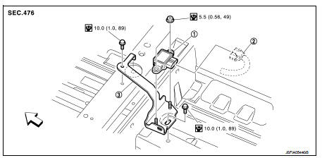
1. Yaw rate/side/decel G sensor
2. Yaw rate/side/decel G sensor harness
connector
3. Bracket
 : Vehicle front
 : N·m (kg-m, in-lb)
Removal and Installation
REMOVAL
CAUTION:
Never drop or strike yaw rate/side/decel G sensor, because it has little
endurance to impact. Never use
a pneumatic tool.
1. Remove front seat (right side).
• 2WD: Refer to SE-19, "Removal and Installation".
• 4WD: Refer to SE-27, "Removal and Installation".
2. Remove floor carpet. Refer to INT-23, "Removal and Installation".
3. Disconnect yaw rate/side/decel G sensor harness connector.
4. Remove yaw rate/side/decel G sensor.
INSTALLATION
Note the following, and install in the reverse order of removal.
• Never drop or strike yaw rate/transverse/decel G sensor, because it has little endurance to impact. Never use a power tool.
 ABS actuator and electric unit (control unit)
Exploded View
LHD
MR16DDT (2WD), HR16DE
1. ABS actuator and electric unit (control
unit)
2. ABS actuator and electric unit (control
unit) harness connector
3. Bracket
A. To front LH caliper ...
 Steering angle sensor
Removal and Installation
REMOVAL
1. Remove spiral cable assembly. Refer to SR-16, "Removal and
Installation".
2. Remove steering angle sensor.
INSTALLATION
Note the following, and i ...
Other materials:
Rear hatch
To access the cargo area and open the rear hatch, unlock the centralized locking system and firmly push the electronic rear hatch opener switch A situated under the molded handle lip. Pull up smoothly on the rear hatch assembly to raise it to its fully extended overhead positio ...
Service data and specifications (SDS)
General Specifications
MR16DDT
HR16DE, K9K
Brake Pedal
Brake Booster
2WD
4WD
Front Disc Brake
MR16DDT
HR16DE, K9K
Rear Disc Brake
...
Hood lock
Exploded View
1. Hood lock control cable assembly
2. Hood lock assembly
: Clip
: N·m (kg-m, ft-lb)
: Body grease
Hood lock
HOOD LOCK : Removal and Installation
REMOVAL
1. Remove front center grille. Refer to EXT-18, "Removal and Installation".
2. Remove crash zone sensor. Ref ...
