Nissan Juke Service and Repair Manual : Liquid Gasket
REMOVAL OF LIQUID GASKET SEALING
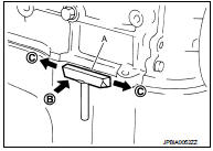
ŌĆó After removing mounting nuts and bolts, separate the mating surface using the seal cutter [SST: KV10111100] (A) and remove old liquid gasket sealing.
CAUTION:
Be careful not to damage the mating surfaces.
ŌĆó Tap the seal cutter [SST: KV10111100] to insert it (B), and then slide it (C) by tapping on the side as shown in the figure.
ŌĆó In areas where the seal cutter [SST: KV10111100] is difficult to use, lightly tap the parts using a plastic hammer to remove it.
CAUTION:
If for some unavoidable reason tool such as a screwdriver is
used, be careful not to damage the mating surfaces
.
LIQUID GASKET APPLICATION PROCEDURE
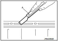
1. Using a scraper (A), remove old liquid gasket adhering to the liquid gasket application surface and the mating surface.
ŌĆó Remove liquid gasket completely from the groove of the liquid gasket application surface, mounting bolts, and bolt holes.
2. Wipe the liquid gasket application surface and the mating surface with white gasoline (lighting and heating use) to remove adhering moisture, grease and foreign materials.
3. Attach liquid gasket tube to the tube presser (commercial service tool).
Use Genuine Liquid Gasket or equivalent.
4. Apply liquid gasket without gaps to the specified location according to the specified dimensions.
ŌĆó If there is a groove for liquid gasket application, apply liquid gasket to the groove.
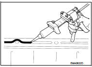
ŌĆó As for bolt holes (B), normally apply liquid gasket inside the holes. Occasionally, it should be applied outside the holes.
Check to read the text of this manual.
A : Groove
 : Inside
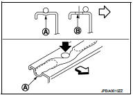
ŌĆó Within five minutes of liquid gasket application, install the mating component.
ŌĆó If liquid gasket protrudes, wipe it off immediately.
ŌĆó Do not retighten mounting bolts or nuts after the installation.
ŌĆó After 30 minutes or more have passed from the installation, fill engine oil and engine coolant.
CAUTION:
If there are specific instructions in this manual, observe them
.
 Parts Requiring Angle Tightening
ŌĆó Use the angle wrench [SST: KV10112100] for the final tightening of the
following engine parts:
- Cylinder head bolts
- Lower cylinder block bolts
- Connecting rod cap bolts
- Crankshaft pull ...
 Precaution for Diesel Equipment
CLEANLINESS
CLEANLINESS INSTRUCTIONS WHICH MUST BE FOLLOWED WHEN WORKING ON THE HIGH
PRESSURE
DIRECT INJECTION SYSTEM
Risks relating to contamination
The system is very sensitive to contaminatio ...
Other materials:
Special Service Tool
HFC-134a (R-134a) Service Tool and Equipment
ŌĆó Never mix HFC-134a (R-134a) refrigerant and/or its specified lubricant with
CFC-12 (R-12) refrigerant and/
or its lubricant.
ŌĆó Separate and non-interchangeable service equipment must be used for handling
each type of refrigerant/
lubricant.
...
P160C ECM
DTC Logic
DTC DETECTION LOGIC
Diagnosis Procedure
1.INSPECTION START
1. Turn ignition switch ON.
2. Erase DTC.
3. Turn ignition switch OFF and wait for 20 seconds.
4. Turn ignition switch ON and perform the self-diagnosis.
Is the DTC P160C displayed again?
YES >> GO TO 2.
NO &g ...
Cooling fan
Diagnosis Procedure
1.CHECK GROUND CONNECTION
1. Turn ignition switch OFF.
2. Check ground connection E38. Refer to Ground Inspection in GI-44, "Circuit
Inspection".
Is the inspection result normal?
YES >> GO TO 2.
NO >> Repair or replace ground connection.
2.CHE ...
