Nissan Juke Service and Repair Manual : U0140 lost communication (BCM)
Description
CAN (Controller Area Network) is a serial communication line for real-time application. It is an on-vehicle multiplex communication line with high data communication speed and excellent malfunction detection ability.
Many electronic control units are equipped onto a vehicle, and each control unit shares information and links with other control units during operation (not independently). In CAN communication, control units are connected with 2 communication lines (CAN-H line, CAN-L line) allowing a high rate of information transmission with less wiring. Each control unit transmits/receives data but selectively reads required data only.
DTC Logic
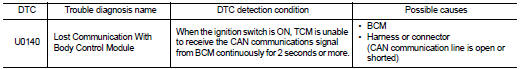
DTC DETECTION LOGIC
DTC CONFIRMATION PROCEDURE
1.PREPARATION BEFORE WORK
If another “DTC CONFIRMATION PROCEDURE” occurs just before, turn ignition switch OFF and wait for at least 10 seconds, then perform the next test.
>> GO TO 2.
2.PERFORM DTC CONFIRMATION PROCEDURE
 With CONSULT-III
1. Start the engine and wait for at least 5 seconds.
2. Check the DTC.
Is “U0140” detected? YES >> Go to TM-392, "Diagnosis Procedure".
NO >> INSPECTION END
Diagnosis Procedure
For the diagnosis procedure, refer to LAN-17, "Trouble Diagnosis Flow Chart".
 U0100 lost communication (ECM A)
Description
CAN (Controller Area Network) is a serial communication line for real-time
application. It is an on-vehicle multiplex
communication line with high data communication speed and excellen ...
 U0141 lost communication (BCM A)
Description
CAN (Controller Area Network) is a serial communication line for real-time
application. It is an on-vehicle multiplex
communication line with high data communication speed and excellen ...
Other materials:
Additional service when removing battery negative terminal
Description
• The NAVI control unit is equipped with the anti-theft system.
• The NAVI control unit operates after authenticating a fixed four-digit
anti-theft code.
• After removing the battery of the NAVI control unit, the authentication of the
anti-theft code is required.
Work Proce ...
Blower motor
Exploded View
2WD models
1. A/C unit assembly
2. Fan control amp.*1
3. Blower fan resistor*2
4. Blower motor
5. Blower motor cover
• *1: Automatic air conditioner
• *2: Manual air conditioner or Manual heater
4WD models
1. A/C unit assembly
2. Blower fan resistor*1
3. Sub ha ...
Information display (speed limiter))
Component Function Check
1.CHECK INFORMATION DISPLAY (SPEED LIMITER) FUNCTION
1. Start engine.
2. Press speed limiter MAIN switch.
3. Drive the vehicle at more than 30 km/h (20 MPH).
CAUTION:
Always drive vehicle at a safe speed.
4. Press SET/ACCELERATE or SET/COAST switch.
5. Perform a te ...
