Nissan Juke Service and Repair Manual : System
Engine control system : System Diagram
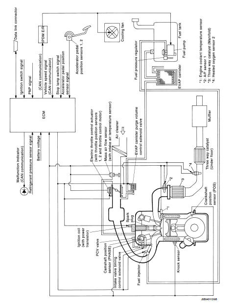
Engine control system : System Description
ECM performs various controls such as fuel injection control and ignition timing control.
MULTIPORT FUEL INJECTION SYSTEM
Multiport fuel injection system : System Diagram
Multiport fuel injection system : System Description
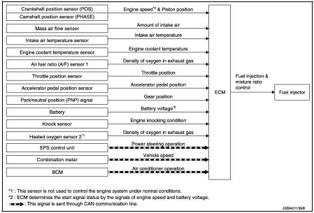
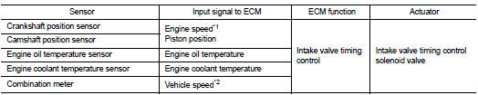
INPUT/OUTPUT SIGNAL CHART
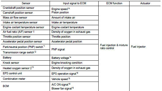
*1: M/T models
*2: CVT models
*3: This sensor is not used to control the engine system under normal
conditions.
*4: ECM determines the start signal status by the signals of engine speed and battery voltage.
*5: This signal is sent to the ECM through CAN communication line.
SYSTEM DESCRIPTION
The amount of fuel injected from the fuel injector is determined by the ECM. The ECM controls the length of time the valve remains open (injection pulse duration). The amount of fuel injected is a program value in the ECM memory. The program value is preset by engine operating conditions. These conditions are determined by input signals (for engine speed and intake air) from the crankshaft position sensor, camshaft position sensor and the mass air flow sensor.
VARIOUS FUEL INJECTION INCREASE/DECREASE COMPENSATION
In addition, the amount of fuel injected is compensated to improve engine performance under various operating conditions as listed below.
<Fuel increase>
ŌĆó During warm-up
ŌĆó When starting the engine
ŌĆó During acceleration
ŌĆó Hot-engine operation
ŌĆó When selector lever position is changed from N to D (CVT models)
ŌĆó High-load, high-speed operation
<Fuel decrease>
ŌĆó During deceleration
ŌĆó During high engine speed operation
MIXTURE RATIO FEEDBACK CONTROL (CLOSED LOOP CONTROL)
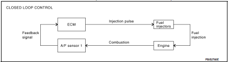
The mixture ratio feedback system provides the best air-fuel mixture ratio for drivability and emission control.
The three way catalyst (manifold) can better reduce CO, HC and NOx emissions. This system uses A/F sensor 1 in the exhaust manifold to monitor whether the engine operation is rich or lean. The ECM adjusts the injection pulse width according to the sensor voltage signal. For more information about A/F sensor 1, refer to EC-459, "Air Fuel Ratio Sensor 1". This maintains the mixture ratio within the range of stoichiometric (ideal airfuel mixture).
This stage is referred to as the closed loop control condition.
Heated oxygen sensor 2 is located downstream of the three way catalyst (manifold). Even if the switching characteristics of A/F sensor 1 shift, the air-fuel ratio is controlled to stoichiometric by the signal from heated oxygen sensor 2.
ŌĆó Open Loop Control
The open loop system condition refers to when the ECM detects any of the
following conditions. Feedback
control stops in order to maintain stabilized fuel combustion.
- Deceleration and acceleration
- High-load, high-speed operation
- Malfunction of A/F sensor 1 or its circuit
- Insufficient activation of heated sensor 1 at low engine coolant temperature
- High engine coolant temperature
- During warm-up
- After shifting from N to D (CVT models)
- When starting the engine
MIXTURE RATIO SELF-LEARNING CONTROL
The mixture ratio feedback control system monitors the mixture ratio signal transmitted from A/F sensor 1.
This feedback signal is then sent to the ECM. The ECM controls the basic mixture ratio as close to the theoretical mixture ratio as possible. However, the basic mixture ratio is not necessarily controlled as originally designed. Both manufacturing differences (i.e., mass air flow sensor hot wire) and characteristic changes during operation (i.e., fuel injector clogging) directly affect mixture ratio.
Accordingly, the difference between the basic and theoretical mixture ratios is monitored in this system. This is then computed in terms of ŌĆ£injection pulse durationŌĆØ to automatically compensate for the difference between the two ratios.
ŌĆ£Fuel trimŌĆØ refers to the feedback compensation value compared against the basic injection duration. Fuel trim includes ŌĆ£short-term fuel trimŌĆØ and ŌĆ£long-term fuel trimŌĆØ.
ŌĆ£Short-term fuel trimŌĆØ is the short-term fuel compensation used to maintain the mixture ratio at its theoretical value. The signal from A/F sensor 1 indicates whether the mixture ratio is RICH or LEAN compared to the theoretical value. The signal then triggers a reduction in fuel volume if the mixture ratio is rich, and an increase in fuel volume if it is lean.
ŌĆ£Long-term fuel trimŌĆØ is overall fuel compensation carried out long-term to compensate for continual deviation of the ŌĆ£short-term fuel trimŌĆØ from the central value. Such deviation will occur due to individual engine differences, wear over time and changes in the usage environment.
FUEL INJECTION TIMING
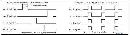
Two types of systems are used.
ŌĆó Sequential Multiport Fuel Injection System Fuel is injected into each cylinder during each engine cycle according to the firing order. This system is used when the engine is running.
ŌĆó Simultaneous Multiport Fuel Injection System Fuel is injected simultaneously into all four cylinders twice each engine cycle. In other words, pulse signals of the same width are simultaneously transmitted from the ECM.
The four injectors will then receive the signals two times for each engine cycle.
This system is used when the engine is being started and/or if the fail safe system (CPU) is operating.
FUEL SHUT-OFF
Fuel to each cylinder is cut off during deceleration, operation of the engine at excessively high speeds or operation of the vehicle at excessively high speeds.
Electric ignition system : System Diag
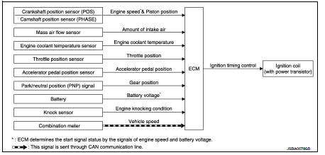
Electric ignition system : System Description
INPUT/OUTPUT SIGNAL CHART
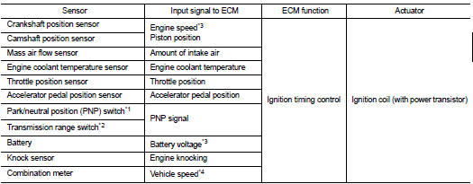
*1: M/T models
*2: CVT models
*3: ECM determines the start signal status by the signals of engine speed and
battery voltage.
*4: This signal is sent to the ECM through CAN communication line.
SYSTEM DESCRIPTION
Firing order: 1 - 3 - 4 - 2
The ignition timing is controlled by the ECM to maintain the best air-fuel ratio for every running condition of the engine. The ignition timing data is stored in the ECM.
The ECM receives information such as the injection pulse width and camshaft position sensor signal. Computing this information, ignition signals are transmitted to the power transistor.
During the following conditions, the ignition timing is revised by the ECM according to the other data stored in the ECM.
ŌĆó At starting
ŌĆó During wa
rm-up
ŌĆó At idle
ŌĆó At low battery voltage
ŌĆó During acceleration
The knock sensor retard system is designed only for emergencies. The basic ignition timing is programmed within the anti-knocking zone, if recommended fuel is used under dry conditions. The retard system does not operate under normal driving conditions. If engine knocking occurs, the knock sensor monitors the condition.
The signal is transmitted to the ECM. The ECM retards the ignition timing to eliminate the knocking condition.
Air conditioning cut control : System Diagram
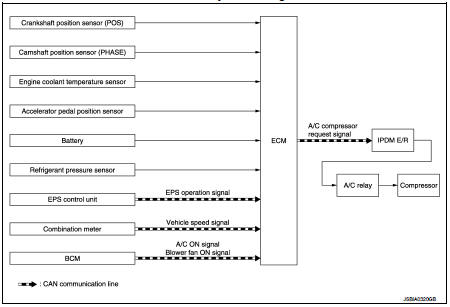
Air conditioning cut control : System Description
INPUT/OUTPUT SIGNAL CHART
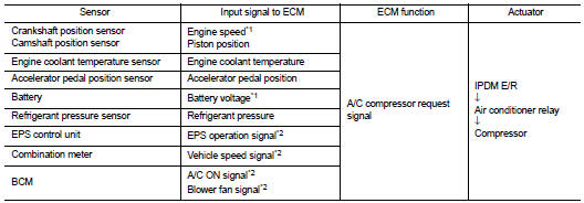
*1: ECM determines the start signal status by the signals of engine speed and battery voltage.
*2: This signal is sent to the ECM through CAN communication line.
SYSTEM DESCRIPTION
This system improves engine operation when the air conditioner is used.
Under the following conditions, the air conditioner is turned off.
ŌĆó When the accelerator pedal is fully depressed.
ŌĆó When cranking the engine.
ŌĆó At high engine speeds.
ŌĆó When the engine coolant temperature becomes excessively high.
ŌĆó When operating power steering during low engine speed or low vehicle speed.
ŌĆó When engine speed is excessively low.
ŌĆó When refrigerant pressure is excessively low or high.
Automatic speed control device (ASCD) : System Diagram
Automatic speed control device (ASCD) : System Description
INPUT/OUTPUT SIGNAL CHART
*: This signal is sent to the ECM via the CAN communication line
BASIC ASCD SYSTEM
ŌĆó Automatic Speed Control Device (ASCD) allows a driver to keep vehicle at predetermined constant speed without depressing accelerator pedal. Driver can be set the vehicle speed in the set speed range.
ŌĆó ECM controls throttle angle of electric throttle control actuator to regulate engine speed.
ŌĆó Operation status of ASCD is indicated in combination meter.
ŌĆó If any malfunction occurs in the ASCD system, it automatically deactivates the ASCD control.
Refer to EC-487, "AUTMATIC SPEED CONTROL DEVICE (ASCD) : Switch Name and Function" for ASCD operating instructions.
CAUTION:
Always drive vehicle in a safe manner according to traffic conditions and obey
all traffic laws.
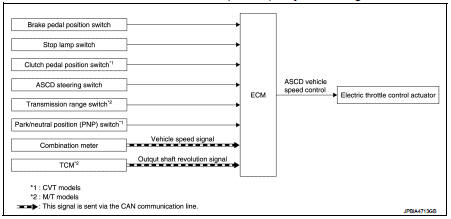
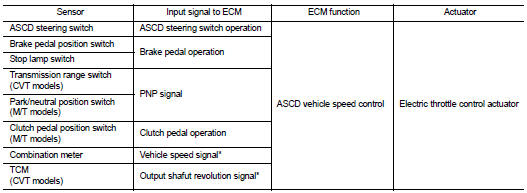
Speed limiter : System Diagram
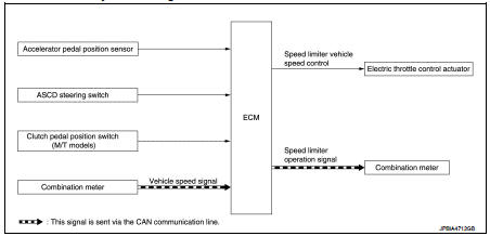
Speed limiter : System Description
INPUT/OUTPUT SIGNAL CHART
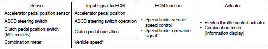
*: This signal is sent to the ECM through CAN communication line
BASIC SPEED LIMITER SYSTEM
ŌĆó Speed limiter is a system that enables to restrict the vehicle speed within the set speed that is selected by the driver. Driver can be set the vehicle speed in the set speed range.
ŌĆó ECM controls throttle angle of electric throttle control actuator to regulate vehicle speed.
ŌĆó Operation status of speed limiter is indicated on the information display in the combination meter.
ŌĆó Unlike cancel conditions for ASCD, the speed limiter is not cancelled even when the clutch pedal is depressed. ECM detects a clutch pedal position switch signal and controls engine revolutions to maintain a set speed when shifting gears.
ŌĆó If any malfunction occurs in speed limiter system, it automatically deactivates the speed limiter control.
Refer to EC-488, "SPEED LIMITER : Switch Name and Function" for speed limiter operating instructions.
CAUTION:
Always drive vehicle in safe manner according to traffic conditions and obey all
traffic laws.
NOTE:
Since the speed limiter is controlled by the electric throttle control actuator, vehicle speed may exceed a set speed during downhill driving.
CAN communication : System Description
CAN (Controller Area Network) is a serial communication line for real time application. It is an on-vehicle multiplex communication line with high data communication speed and excellent error detection ability. Many electronic control units are equipped onto a vehicle, and each control unit shares information and links with other control units during operation (not independent). In CAN communication, control units are connected with 2 communication lines (CAN H line, CAN L line) allowing a high rate of information transmission with less wiring.
Each control unit transmits/receives data but selectively reads required data only.
Refer to LAN-31, "CAN COMMUNICATION SYSTEM : CAN Communication Signal Chart", about CAN communication for detail.
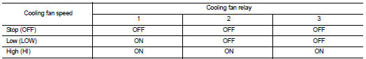
Cooling fan control : System Diagram
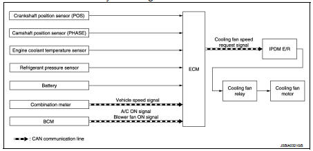
Cooling fan control : System Description
INPUT/OUTPUT SIGNAL CHART
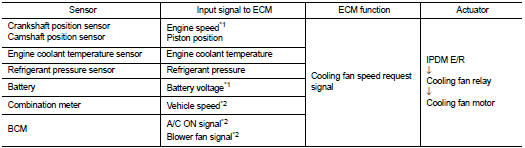
*1: The ECM determines the start signal status by the signals of engine speed and battery voltage.
*2: This signal is sent to ECM through CAN communication line.
SYSTEM DESCRIPTION
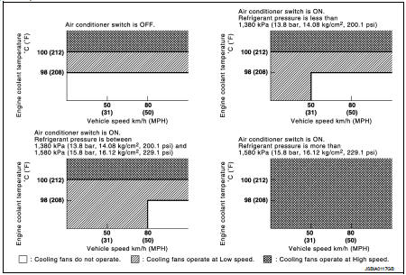
ECM controls cooling fan speed corresponding to vehicle speed, engine coolant temperature, refrigerant pressure, air conditioner ON signal. Then control system has 3-step control [HIGH/LOW/OFF].
Cooling Fan Operation
Cooling Fan Relay Operation
The ECM controls cooling fan relays through CAN communication line.
Evaporative emission system : System Diagram
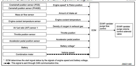
Evaporative emission system : System Description
INPUT/OUTPUT SIGNAL CHART
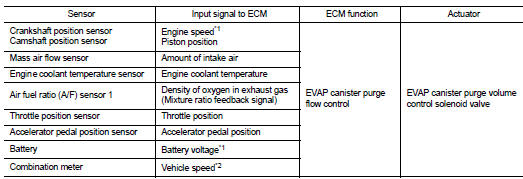
*1: ECM determines the start signal status by the signals of engine speed and battery voltage.
*2: This signal is sent to the ECM through CAN communication line.
SYSTEM DESCRIPTION
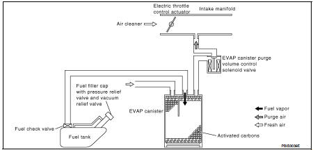
The evaporative emission system is used to reduce hydrocarbons emitted into the atmosphere from the fuel system. This reduction of hydrocarbons is accomplished by activated charcoals in the EVAP canister.
The fuel vapor in the sealed fuel tank is led into the EVAP canister which contains activated carbon and the vapor is stored there when the engine is not operating or when refueling to the fuel tank.
The vapor in the EVAP canister is purged by the air through the purge line to the intake manifold when the engine is operating. EVAP canister purge volume control solenoid valve is controlled by ECM. When the engine operates, the flow rate of vapor controlled by EVAP canister purge volume control solenoid valve is proportionally regulated as the air flow increases.
EVAP canister purge volume control solenoid valve also shuts off the vapor purge line during decelerating and idling.
Intake valve timing control : System Diagram
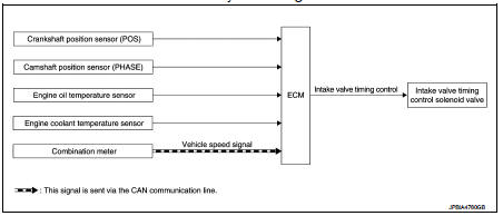
Intake valve timing control : System Description
INPUT/OUTPUT SIGNAL CHART
*1: ECM determines the start signal status by the signals of engine speed and battery voltage.
*2: This signal is sent to the ECM through CAN communication line.
SYSTEM DESCRIPTION
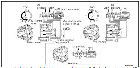
This mechanism hydraulically controls cam phases continuously with the fixed operating angle of the intake valve.
The ECM receives signals such as crankshaft position, camshaft position, engine speed, engine oil temperature and engine coolant temperature. Then, the ECM sends ON/OFF pulse duty signals to the intake valve timing (IVT) control solenoid valve depending on driving status. This makes it possible to control the shut/open timing of the intake valve to increase engine torque in low/mid speed range and output in high-speed range.
Exhaust valve timing control : System Diagram
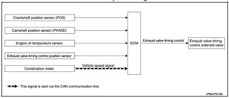
Exhaust valve timing controlL : System Description
INPUT/OUTPUT SIGNAL CHART
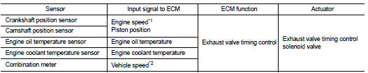
*1: ECM determines the start signal status by the signals of engine speed and battery voltage.
*2: This signal is sent to the ECM through CAN communication line.
SYSTEM DESCRIPTION
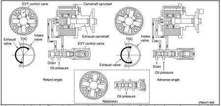
This mechanism hydraulically controls cam phases continuously with the fixed operating angle of the exhaust valve.
The ECM receives signals such as crankshaft position, camshaft position, engine speed, engine oil temperature and engine coolant temperature. Then, the ECM sends ON/OFF pulse duty signals to the exhaust valve timing (EVT) control solenoid valve depending on driving status. This makes it possible to control the shut/ open timing of the exhaust valve to increase engine torque and output in a range of high engine speed
Starter motor drive control : System Diagram
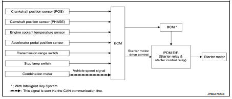
Starter motor drive control : System Description
INPUT/OUTPUT SIGNAL CHART
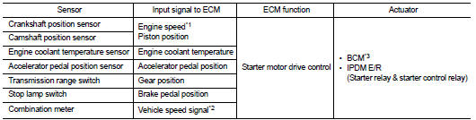
*1: ECM determines the start signal status by the signals of engine speed and battery voltage.
*2: This signal is sent to the ECM through CAN communication line.
*3: With Intelligent Key system
SYSTEM DESCRIPTION
When rapid deceleration occurs during engine runs or idle speed decreases due to heavy load conditions, ECM detects a decrease in idle speed and restarts the engine to secure reliability in handleability by transmitting a cranking request signal to IPDM E/R for activating the starter motor under the following conditions: ŌĆó Selector lever: P or any position other than N ŌĆó Idle switch: ON (Accelerator pedal not depressed) ŌĆó Brake switch: ON (Brake pedal depressed)
Models with no Intelligent Key System transmit a control signal directly to IPDM E/R. On the other hand, models with the Intelligent Key System transmit a control signal to IPDM E/R by way of BCM via CAN communication.
IPDM E/R detects an operating state of the starter motor relay and the starter motor control relay and transmits a feed back signal to ECM via CAN Communication.
Engine protection control at low engine oil pressure : System Diagram
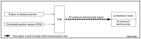
Engine protection control at low engine oil pressure : System Description
INPUT/OUTPUT SIGNAL CHART
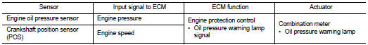
SYSTEM DESCRIPTION
ŌĆó The engine protection control at low engine oil pressure warns the driver of a decrease in engine oil pressure by the oil pressure warning lamp a before the engine becomes damaged.
ŌĆó When detecting a decrease in engine oil pressure at an engine speed less than 1,000 rpm, ECM transmits an oil pressure warning lamp signal to the combination meter.The combination meter turns ON the oil pressure warning lamp, according to the signal.
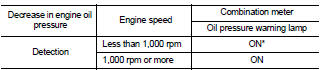
*: When detecting a normal engine oil pressure, ECM turns OFF the oil pressure warning lamp.
NISSAN dynamic control system : System Diagram
CVT models
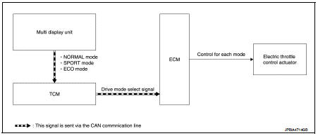
M/T models
NISSAN dynamic control system : System Description
CVT models
System Description
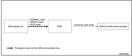
TCM transmits a drive mode select signal to ECM via CAN communication, according
to a NORMAL mode
signal, SPORT mode signal, or ECO mode signal received from the multi display
unit via CAN communication.
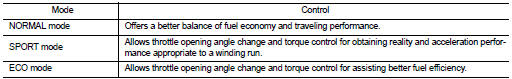
ECM controls torque and throttle opening angle characteristics appropriate for each mode, based on a received drive mode select signal.
NOTE
:
ŌĆó Because of the multi display unit operation, the display may indicate that the
mode is switching. However,
the mode may not actually switch due to CAN communication error.
ŌĆó When a CAN communication error occurs between ECM and TCM, the mode switches to NORMAL mode.
M/T models
System Description
ECM controls torque and throttle opening angle characteristics appropriate for
each mode, based on a NORMAL
mode signal, SPORT mode signal, or ECO mode signal received from the multi
display unit via CAN
communication.
NOTE
:
ŌĆó Because of the multi display unit operation, the display may indicate that the
mode is switching. However,
the mode may not actually switch due to CAN communication error.
ŌĆó When a CAN communication error occurs between ECM and the multi display unit, the mode switches to NORMAL mode.
Control By Mode
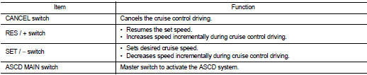
Autmatic speed control device (ASCD) : Switch Name and Function
SWITCHES AND INDICATORS
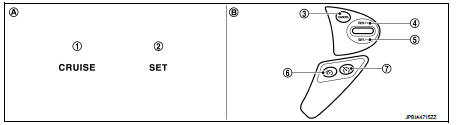
1. CRUISE indicator
2. SET indicator
3. CANCEL switch
4. RES / + switch
5. SET / − switch
6. Speed limiter MAIN Switch
7. ASCD MAIN switch
A. On the combination meter
(Information display)
B. On the steering wheel
SET SPEED RANGE
ASCD system can be set the following vehicle speed.

SWITCH OPERATION
SET OPERATION
Press MAIN switch. (The CRUISE indicator in combination meter illuminates.) When vehicle speed reaches a desired speed between approximately 40 km/h (25 MPH) and 194 km/h (120 MPH), press SET/− switch. (Then SET indicator in combination meter illuminates.) ACCELERATE OPERATION
If the RES/+ switch is pressed during cruise control driving, increase the vehicle speed until the switch is released or vehicle speed reaches maximum speed controlled by the system.
And then ASCD will keep the new set speed.
CANCEL OPERATION
When any of following conditions exist, cruise operation will be canceled.
ŌĆó CANCEL switch is pressed
ŌĆó More than 2 switches at ASCD steering switch are pressed at the same time (Set
speed will be cleared)
ŌĆó Brake pedal is depressed
ŌĆó Clutch pedal is depressed or gear position is changed to neutral position.
(M/T models)
ŌĆó Selector lever is changed to N, P or R position (CVT models)
ŌĆó Vehicle speed decreased to 13 km/h (8 MPH) lower than the set speed
ŌĆó TCS system is operated
When the ECM detects any of the following conditions, the ECM will cancel the
cruise operation and inform
the driver by blinking indicator lamp.
ŌĆó Engine coolant temperature is slightly higher than the normal operating temperature, CRUISE indicator may blink slowly.
When the engine coolant temperature decreases to the normal operating temperature, CRUISE indicator will stop blinking and the cruise operation will be able to work by pressing SET/− switch or RES/+ switch.
ŌĆó Malfunction for some self-diagnoses regarding ASCD control: SET indicator will blink quickly.
If MAIN switch is turned to OFF during ASCD is activated, all of ASCD operations will be canceled and vehicle speed memory will be erased.
COAST OPERATION
When the SET/− switch is pressed during cruise control driving, decrease vehicle set speed until the switch is released. And then ASCD will keep the new set speed.
RESUME OPERATION
When the RES/+ switch is pressed after cancel operation other than pressing MAIN switch is performed, vehicle speed will return to last set speed. To resume vehicle set speed, vehicle condition must meet following conditions.
ŌĆó Brake pedal is released ŌĆó Clutch pedal is released (M/T models) ŌĆó Selector lever is in other than P and N positions (CVT models) ŌĆó Vehicle speed is greater than 40 km/h (25 MPH) and less than 194 km/h (120 MPH)
Speed limiter : Switch Name and Function
SWITCHES AND INDICATORS
NOTE
:
Shared with ASCD switch.
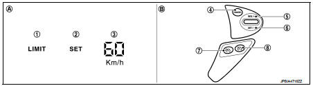
1. Speed limiter indicator
2. SET indicator
3. Set speed indicator
4. CANCEL switch
5. RES / + switch
6. SET / − switch
7. Speed limiter MAIN Switch
8. ASCD MAIN switch
A. On the combination meter
(Information display)
B. On the steering wheel
SET SPEED RANGE
Speed limiter system can be set the following vehicle speed.

SWITCH OPERATION
SET OPERATION
ŌĆó Press speed limiter MAIN switch. (LIMIT indicated on the information
display)
ŌĆó By pressing the SET/− switch, the vehicle speed can be set within the range
between 30 km/h and 210 km/h
(in the metric system mode) or 20 MPH and 130 MPH (in the yard/pound system
mode). (SET and set speed
is indicated on the information display)
ŌĆó When pressing the RES/+ switch, the set speed can be increased.
ŌĆó When pressing the SET/− switch, the set speed can be decreased.
CANCEL CONDITION
ŌĆó When any of following conditions exist, speed limiter control is canceled.
- Speed limiter MAIN switch is pressed. (Set speed is cleared.) - ASCD MAIN switch is pressed. (Set speed is cleared.) - CANCEL switch is pressed.
ŌĆó When accelerator pedal is fully depressed (Kickdown), speed limiter control is temporarily released. And driver can be driven above set speed (Set speed indicator is blinked).
ŌĆó When the ECM detects any of the following conditions, the ECM cancels the speed limiter operation and informs the driver by blinking speed limiter indicator and SET indicator.
- Malfunction for some self-diagnosis regarding ASCD system.
RESUME OPERATION
After the speed limiter is released by other method than the MAIN switch, the RES/+ switch allows to set the vehicle speed again to the one that is previously set before releasing the speed limiter.
 Structure and operation
Positive Crankcase Ventilation
This system returns blow-by gas to the intake manifold.
The positive crankcase ventilation (PCV) valve is provided to conduct crankcase
blow-by gas to the intake ...
 On board diagnostic (OBD) system
Diagnosis Description
This system is an on board diagnostic system that records exhaust
emission-related diagnostic information
and detects a sensors/actuator-related malfunction. A malfunction is ...
Other materials:
Map lamp
Exploded View
1. Map lamp bulb housing
2. Bulb
3. Lens
: Pawl
Removal and Installation
CAUTION:
Disconnect the battery negative terminal or the fuse.
REMOVAL
1. Remove the lens (1).
ŌĆó Insert a remover tool (A) into the gap between the lens.
ŌĆó Disengage the lens fixing pawls, and t ...
RearView Monitor
CAMERA button (used to manually trigger the display views or adjust active screen brightness layouts)
MENU button (opens up global display preferences and system option configuration screens)
WARNING
Failure to follow all safety warnings and t ...
Instrument Panel
Vents: Adjustable climate control outlets for personalized cabin airflow.
Meters and gauges: Comprehensive digital driver information display providing real-time vehicle data.
Center multi-function control panel*: Central hub for infotainment, connec ...
