Nissan Juke Service and Repair Manual : System
Front wiper and washer system (with light & rain sensor)
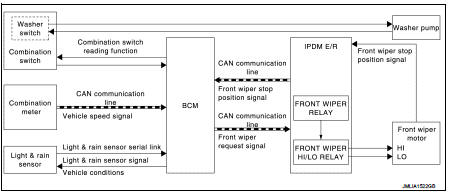
FRONT WIPER AND WASHER SYSTEM (WITH LIGHT & RAIN SENSOR) : System Diagram
FRONT WIPER AND WASHER SYSTEM (WITH LIGHT & RAIN SENSOR) : System Description
OUTLINE
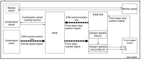
The front wiper is controlled by each function of BCM and IPDM E/R.
Control by BCM
ŌĆó Combination switch reading function
ŌĆó Front wiper control function
Control by IPDM E/R
ŌĆó Front wiper control function
ŌĆó Relay control function
FRONT WIPER BASIC OPERATION
ŌĆó BCM detects the combination switch condition by the combination switch reading function.
ŌĆó BCM transmits the front wiper request signal to IPDM E/R with CAN communication depending on each operating condition of the front wiper.
ŌĆó IPDM E/R turns ON/OFF the integrated front wiper relay and the front wiper high/lo relay according to the front wiper request signal. IPDM E/R provides the power supply to operate the front wiper HI/LO operation.
FRONT WIPER LO OPERATION
ŌĆó BCM transmits the front wiper request signal (LO) to IPDM E/R with CAN communication according to the front wiper LO operating condition.
Front wiper LO operating condition
- Ignition switch ON
- Front wiper switch LO or front wiper switch MIST (while pressing)
ŌĆó IPDM E/R turns ON the integrated front wiper relay according to the front wiper request signal (LO).
FRONT WIPER HI OPERATION
ŌĆó BCM transmits the front wiper request signal (HI) to IPDM E/R with CAN communication according to the front wiper HI operating condition.
Front wiper HI operating condition
- Ignition switch ON
- Front wiper switch HI
ŌĆó IPDM E/R turns ON the integrated front wiper relay and the front wiper high/lo relay according to the front wiper request signal (HI).
FRONT WIPER AUTO OPERATION
ŌĆó BCM receives the wiping speed request signal from the rain sensor with the light and rain sensor serial link.
ŌĆó BCM judges the auto wiping condition depending on the wiping speed request signal and the rain sensor sensitivity setting under front wiper AUTO operating condition.
ŌĆó BCM transmits the front wiper request signals (LO or HI) to the IPDM E/R through CAN communication line according to the auto wiping condition.
Front wiper AUTO operating condition
- Ignition switch ON
- Front wiper switch AUTO
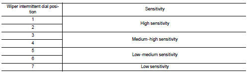
Rain sensor sensitivity setting - BCM determines rain sensor sensitivity according to a wiper volume.
ŌĆó IPDM E/R turns ON the integrated front wiper relay and front wiper HI relay according to the front wiper request signal (LO or HI).
ŌĆó Light and rain sensor transmits rain sensor signal to BCM for HI operation immediately after sensing the raindrops increase under the wiper motor LO operating with the front wiper switch INT.
NOTE
:
Factory setting of the rain sensor operation is operation linked with rain
sensor. Rain sensor operation can be
set to operation linked or not linked with rain sensor using CONSULT-III. Refer
to WW-19, "WIPER : CONSULT-
III Function - WIPER" (With Intelligent Key system) or WW-23, "WIPER :
CONSULT-III Function (BCM -
WIPER)" (Without Intelligent Key system).
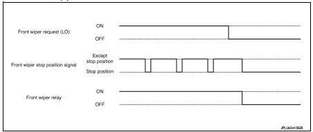
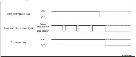
FRONT WIPER AUTO STOP OPERATION
ŌĆó BCM stops transmitting the front wiper request signal when the front wiper switch is turned OFF.
ŌĆó IPDM E/R detects the front wiper stop position signal from the front wiper motor and detects the front wiper motor position (stop position/except stop position).
ŌĆó When the front wiper request signal is stopped, IPDM E/R turns ON the front wiper relay until the front wiper motor returns to the stop position.
NOTE
:
ŌĆó BCM stops the transmitting of the front wiper request signal when the ignition
switch is OFF.
ŌĆó IPDM E/R turns the front wiper relay OFF when the ignition switch is OFF.
Front wiper operation linked with washer
ŌĆó BCM transmits the front wiper request signal (LO) to IPDM E/R with CAN communication according to the washer linked operating condition of the front wiper.
ŌĆó BCM transmits the front wiper request signal (LO) so that the front wiper operates approximately 3 times when the front washer switch OFF is detected.
Washer linked operating condition of front wiper
- Ignition switch ON
- Front washer switch ON (0.4 second or more)
ŌĆó IPDM E/R turns ON the integrated front wiper relay according to the front wiper request signal (LO).
ŌĆó The washer pump is grounded through the combination switch with the front washer switch ON.
FRONT WIPER SERVICE POSITION OPERATION
ŌĆó When front wiper switch is contentiously operated for approximately 1 second, front wiper operates at Lo, stops, and stays in lock back status.
Operation conditions of front wiper service position function - Turn ignition switch OFF (within 1 minutes) - Front wiper switch ON (1 second or more) - Shift position N or P
ŌĆó Front wiper operates at LO and stops, when IPDM E/R detects front wiper request signal from BCM via CAN communication for 1 second, while front wiper position signal is detected at stop position.
ŌĆó Front wioper service position function can be released when combination switch is turned to the ON position within 1 minutes after ignition switch turned to the OFF position. Front wiper service position function can be released when combination switch (either position of INT, LO, HI, MIST, or WASHER) is turned to the ON position 1 minutes or more after ignition switch is turned to the OFF position.
FRONT WIPER AND WASHER SYSTEM (WITH LIGHT & RAIN SENSOR) : Fail-safe
IPDM E/R
When CAN communication with ECM and BCM is impossible, IPDM E/R performs
fail-safe control. After CAN
communication recovers normally, it also returns to normal control.
If No CAN Communication Is Available With BCM
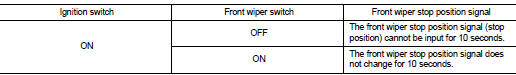
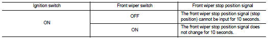
IPDM E/R detects front wiper stop position by a front wiper stop position signal.
When a front wiper stop position signal is in the conditions listed below, IPDM E/R stops power supply to wiper after repeating a front wiper 10 seconds activation and 20 seconds stop five times.
NOTE
:
This operation status can be confirmed on the IPDM E/R ŌĆ£Data MonitorŌĆØ that
displays ŌĆ£BLOCKŌĆØ for the item
ŌĆ£WIP PROTŌĆØ while the wiper is stopped.
BCM
BCM detects the rain sensor serial link error and the rain sensor malfunction.
BCM controls the following fail-safe when rain sensor has a malfunction.
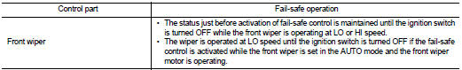
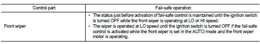
Fail-safe Control
ŌĆó Front wiper control
- Front wiper switch AUTO and sensing rain drop: The condition just before the activation of fail-safe is maintained until the front wiper switch is turned OFF.
- Front wiper switch AUTO and not sensing rain drop: Front wiper is LO operation until the front wiper switch is turned off.
Front wiper and washer system (without light & rain sensor)
FRONT WIPER AND WASHER SYSTEM (WITHOUT LIGHT & RAIN SENSOR) : System Diagram
FRONT WIPER AND WASHER SYSTEM (WITHOUT LIGHT & RAIN SENSOR) : System Description
OUTLINE
The front wiper is controlled by each function of BCM and IPDM E/R.
Control by BCM
ŌĆó Combination switch reading function
ŌĆó Front wiper control function
Control by IPDM E/R
ŌĆó Front wiper control function
ŌĆó Relay control function
FRONT WIPER BASIC OPERATION
ŌĆó BCM detects the combination switch condition by the combination switch reading function.
ŌĆó BCM transmits the front wiper request signal to IPDM E/R with CAN communication depending on each operating condition of the front wiper.
ŌĆó IPDM E/R turns ON/OFF the integrated front wiper relay and the front wiper high relay according to the front wiper request signal. IPDM E/R provides the power supply to operate the front wiper HI/LO operation.
FRONT WIPER LO OPERATION
ŌĆó BCM transmits the front wiper request signal (LO) to IPDM E/R with CAN communication according to the front wiper LO operating condition.
Front wiper LO operating condition
- Ignition switch ON
- Front wiper switch LO or front wiper switch MIST (while pressing)
ŌĆó IPDM E/R turns ON the integrated front wiper relay according to the front wiper request signal (LO).
FRONT WIPER HI OPERATION
ŌĆó BCM transmits the front wiper request signal (HI) to IPDM E/R with CAN communication according to the front wiper HI operating condition.
Front wiper HI operating condition
- Ignition switch ON
- Front wiper switch HI
ŌĆó IPDM E/R turns ON the integrated front wiper relay and the front wiper high relay according to the front wiper request signal (HI).
FRONT WIPER INT OPERATION (LINKED WITH VEHICLE SPEED)
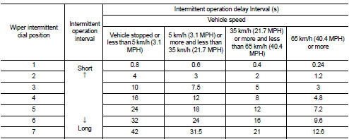
ŌĆó BCM transmits the front wiper request signal (INT) to IPDM E/R with CAN communication according to the front wiper INT operation condition and the intermittent operation delay interval judged value.
Front wiper INT operating condition
- Ignition switch ON
- Front wiper switch INT
Intermittent operation delay interval judgment
- BCM calculates the intermittent operation delay interval from the following
ŌĆó Vehicle speed signal (received from the combination meter with CAN
communication)
ŌĆó Wiper intermittent dial position
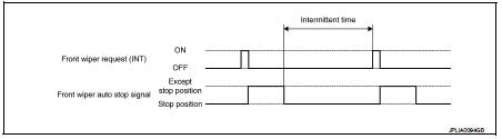
ŌĆó IPDM E/R turns the integrated front wiper relay ON so that the front wiper is operated only once according to the front wiper request signal (INT).
ŌĆó BCM detects stop position/except stop position of the front wiper motor according to the front wiper stop position signal received from IPDM E/R with CAN communication.
ŌĆó BCM transmits the front wiper request signal (INT) again after the intermittent operation delay interval after the front wiper motor is stopped.
NOTE
:
Factory setting of the front wiper intermittent operation is operation linked
with vehicle speed. Front wiper
intermittent operation can be set to operation linked or not linked with vehicle
speed using CONSULT-III. Refer
to WW-19, "WIPER : CONSULT-III Function - WIPER" (With Intelligent Key system)
or WW-23, "WIPER :
CONSULT-III Function (BCM - WIPER)" (Without Intelligent Key system).
Front wiper intermittent operation with vehicle speed
ŌĆó BCM calculates the intermittent operation delay interval from the following
- Vehicle speed signal
- Wiper intermittent dial position
FRONT WIPER AUTO STOP OPERATION
ŌĆó BCM stops transmitting the front wiper request signal when the front wiper switch is turned OFF.
ŌĆó IPDM E/R detects the front wiper stop position signal from the front wiper motor and detects the front wiper motor position (stop position/except stop position).
ŌĆó When the front wiper request signal is stopped, IPDM E/R turns ON the front wiper relay until the front wiper motor returns to the stop position.
NOTE
:
ŌĆó BCM stops the transmitting of the front wiper request signal when the ignition
switch is OFF.
ŌĆó IPDM E/R turns the front wiper relay OFF when the ignition switch is OFF.
FRONT WIPER OPERATION LINKED WITH WASHER
ŌĆó BCM transmits the front wiper request signal (LO) to IPDM E/R with CAN communication according to the washer linked operating condition of the front wiper.
ŌĆó BCM transmits the front wiper request signal (LO) so that the front wiper operates approximately 3 times when the front washer switch OFF is detected.
Washer linked operating condition of front wiper
- Ignition switch ON
- Front washer switch ON (0.4 second or more)
ŌĆó IPDM E/R turns ON the integrated front wiper relay according to the front wiper request signal (LO).
ŌĆó The washer pump is grounded through the combination switch with the front washer switch ON.
FRONT WIPER SERVICE POSITION OPERATION
ŌĆó When front wiper switch is contentiously operated for approximately 1 second, front wiper operates at Lo, stops, and stays in lock back status.
Operation conditions of front wiper service position function - Turn ignition switch OFF (within 1 minutes) - Front wiper switch ON (1 second or more) - Shift position N or P<
ŌĆó Front wiper operates at LO and stops, when IPDM E/R detects front wiper request signal from BCM via CAN communication for 1 second, while front wiper position signal is detected at stop position.
ŌĆó Front wioper service position function can be released when combination switch is turned to the ON position within 1 minutes after ignition switch turned to the OFF position. Front wiper service position function can be released when combination switch (either position of INT, LO, HI, MIST, or WASHER) is turned to the ON position 1 minutes or more after ignition switch is turned to the OFF position.
FRONT WIPER AND WASHER SYSTEM (WITHOUT LIGHT & RAIN SENSOR) : Failsafe
IPDM E/R
When CAN communication with ECM and BCM is impossible, IPDM E/R performs
fail-safe control. After CAN
communication recovers normally, it also returns to normal control.
If No CAN Communication Is Available With BCM
IPDM E/R detects front wiper stop position by a front wiper stop position signal.
When a front wiper stop position signal is in the conditions listed below, IPDM E/R stops power supply to wiper after repeating a front wiper 10 seconds activation and 20 seconds stop five times.
NOTE
:
This operation status can be confirmed on the IPDM E/R ŌĆ£Data MonitorŌĆØ that
displays ŌĆ£BLOCKŌĆØ for the item
ŌĆ£WIP PROTŌĆØ while the wiper is stopped.
BCM
BCM detects the rain sensor serial link error and the rain sensor malfunction.
BCM controls the following fail-safe when rain sensor has a malfunction.
Fail-safe Control
ŌĆó Front wiper control
- Front wiper switch AUTO and sensing rain drop: The condition just before the
activation of fail-safe is maintained
until the front wiper switch is turned OFF.
- Front wiper switch AUTO and not sensing rain drop: Front wiper is LO operation until the front wiper switch is turned off.
Rear wiper and washer system
REAR WIPER AND WASHER SYSTEM : System Diagram
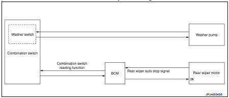
REAR WIPER AND WASHER SYSTEM : System Description
OUTLINE
The rear wiper is controlled by each function of BCM.
Control by BCM
ŌĆó Combination switch reading function
ŌĆó Rear wiper control function
REAR WIPER BASIC OPERATION
ŌĆó BCM detects the combination switch condition by the combination switch reading function.
ŌĆó BCM controls the rear wiper to start or stop.
REAR WIPER ON OPERATION
ŌĆó BCM supplies power to the rear wiper motor according to the rear wiper ON operating condition.
Rear wiper ON operating condition
- Ignition switch ON
- Rear wiper switch ON
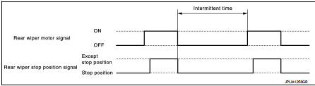
REAR WIPER INT OPERATION
ŌĆó BCM supplies power to the rear wiper motor according to the INT operating condition.
Rear wiper INT operating condition
- Ignition switch ON
- Rear wiper switch INT
ŌĆó BCM controls the rear wiper to operate once.
ŌĆó BCM detects the rear wiper motor stopping position.
ŌĆó BCM supplies power to the rear wiper motor after an intermittent from the stop of the rear wiper motor.
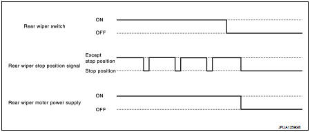
REAR WIPER AUTO STOP OPERATION
ŌĆó BCM stops supplying power to the rear wiper motor when the rear wiper switch is turned OFF.
ŌĆó BCM reads a rear wiper stop position signal from the rear wiper motor to detect a rear wiper motor position.
ŌĆó When the rear wiper motor is at other than the stopping position, BCM continues to supply power to the rear wiper motor until it returns to the stopping position.
NOTE
:
BCM stops supplying power to the rear wiper motor when the ignition switch is
turned OFF.
REAR WIPER OPERATION LINKED WITH WASHER
ŌĆó BCM supplies power to the rear wiper motor according to the washer linked operating condition of rear wiper. When the rear washer switch is turned OFF, BCM controls rear wiper to operate approximately 3 times.
Washer linked operating condition of rear wiper
- Ignition switch ON
- Rear washer switch ON (0.4 second or more)
ŌĆó The washer pump is grounded through the combination switch with the rear washer switch ON.
REAR WIPER AND WASHER SYSTEM : Fail-safe
REAR WIPER MOTOR PROTECTION
BCM detects the rear wiper stopping position according to the rear wiper stop position signal.
When the rear wiper stop position signal does not change for more than 5 seconds while driving the rear wiper, BCM stops power supply to protect the rear wiper motor.
Condition of cancellation 1. More than 1 minute is passed after the rear wiper stop.
2. Turn rear wiper switch OFF.
3. Operate the rear wiper switch or rear washer switch.
Head lamp washer system
HEAD LAMP WASHER SYSTEM : System Diagram
HEAD LAMP WASHER SYSTEM : System Description
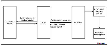
OUTLINE
Headlamp washer is controlled by each function of BCM and IPDM E/R.
Control by BCM
ŌĆó Combination switch reading function
ŌĆó Headlamp washer control function
Control by IPDM E/R ŌĆó Headlamp washer relay control function
HEADLAMP WASHER OPERATION
ŌĆó BCM detects the combination switch condition by the combination switch reading function.
ŌĆó BCM transmits the headlamp washer request signal to IPDM E/R with CAN communication depending on each operating condition of the headlamp washer.
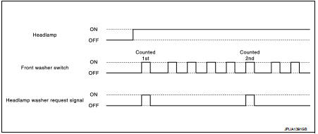
Operation is front washer switch (The first time)
- Ignition switch ON
- Headlamps ON
- Front washer switch ON at first time
Operation is front washer switch (From the second time)
- Ignition switch ON
- Headlamps ON
- Front washer switch ON at fifth time after the first time
ŌĆó IPDM E/R turns ON/OFF the headlamp washer relay by receiving the headlamp washer request signal, and controls the headlamp washer.
HEAD LAMP WASHER SYSTEM : Fail-s
IPDM E/R
When CAN communication with ECM and BCM is impossible, IPDM E/R performs
fail-safe control. After CAN
communication recovers normally, it also returns to normal control.
If No CAN Communication Is Available With BCM

 Component parts
Component Parts Location
1. Light & rain sensor*1
2. Combination switch
3. Combination meter
4. BCM
Refer to BCS-6, "BODY CONTROL
SYSTEM : Component Parts Location".
5. IPDM E ...
 Diagnosis system (BCM) (with intelligent key system)
Common item
COMMON ITEM : CONSULT-III Function (BCM - COMMON ITEM)
APPLICATION ITEM
CONSULT-III performs the following functions via CAN communication with BCM.
SYSTEM APPLICATION
BCM can perfo ...
Other materials:
Speedometer and odometer
Your Nissan Leaf is equipped with a high-visibility digital speedometer and a precise odometer system. The speedometer is positioned conveniently on the right side of the main vehicle information display, while the odometer and trip data are integrated directly into the vehicle information screen fo ...
Wheel Alignment
2WD
Measure value under unladen*2 conditions.
*1: A difference when assuming the left side a standard.
*2: Fuel, engine coolant and lubricant are full. Spare tire, jack, hand tools
and mats are in designated positions.
4WD
Measure value under unladen*2 conditions.
*1: A differenc ...
P1217 engine over temperature
DTC Logic
DTC DETECTION LOGIC
NOTE:
ŌĆó If DTC P1217 is displayed with DTC U1001, first perform the trouble diagnosis
for DTC U1001. Refer
to EC-569, "DTC Logic".
ŌĆó If DTC P1217 is displayed with DTC P0607, first perform the trouble diagnosis
for DTC P0607. Refer
to EC-685, &qu ...
