Nissan Juke Service and Repair Manual : Spiral cable
Exploded View
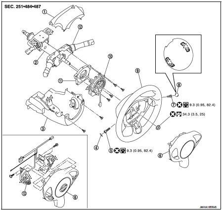
1. Steering column upper cover
2. Steering column assembly
3. Steering column lower cover
4. Side lid LH
5. TORX bolt
6. Driver air bag module
7. TORX bolt
8. Side lid RH
9. Steering wheel
10. Spiral cable
11. Steering angle sensor
12. Combination switch
13. Steering switch
 : Pawl
 : Do not reuse
 : N·m (kg-m, in-lb)
 : N·m (kg-m, ft-lb)
Removal and Installation
WARNING:
• Before servicing, turn ignition switch OFF, disconnect battery negative
terminal and wait 3 minutes
or more.
• Never use the air tools or electric tools for servicing.
REMOVAL
1. Remove driver air bag module. Refer to SR-13, "Removal and Installation".
2. Remove steering wheel. Refer to ST-9, "Removal and Installation".
3. Remove steering column upper cover and steering column lower cover. Refer to IP-13, "Removal and Installation".
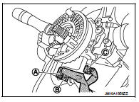
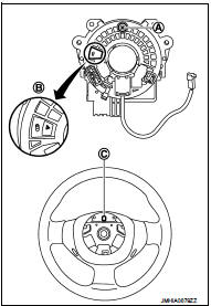
4. Disconnect the spiral cable body side harness connectors (A), (B) and steering angle sensor harness connectors (C).
NOTE
:
Disconnect the spiral cable body side harness connector (B)
after removing the spiral cable (A).
5. Remove the spiral cable fixing screws.
6. Remove the spiral cable fixing pawls with remover tool (A).
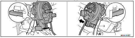
 : Pawl
CAUTION:
Remove pawls slowly so that they are not damaged.
7. Remove the steering angle sensor. Refer to BRC-236, "Removal and Installation".
CAUTION:
• Never impact the spiral cable.
• Replace the spiral cable if it is dropped or sustains an impact.
• Never disassemble the spiral cable.
• Never apply lubricant to the spiral cable.
• Never allow oil, grease, detergent, or water to come in contact with the spiral cable.
INSTALLATION
Note the following items, and then install in the reverse order of removal.
CAUTION
:
• The spiral cable may snap during steering operation if the
cable is installed in an improper position. The neutral position is set as per
the following.
• Carefully turn the spiral cable clockwise to the end position.
Then turn it counterclockwise (about 2 and a half turns) and stop turning at the mark (B) when the stopper insertion holes are in the same position.
• The service part is installed in the neutral position by the stopper and can be set without adjusting after the stopper is removed.
• Never over turn the spiral cable or go beyond the number of turns required. (This causes the cable to snap) • Adjust the spiral cable locating pin (A) to the steering wheel locating pin hole (C).
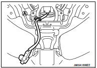
• Fix the driver air bag module harnesses to the harness fixing hook (A).
• If malfunction is detected by the air bag warning lamp, after repair or replacement of the malfunctioning parts, reset the memory using self-diagnosis or CONSULT-III. Refer to SRC-12, "On Board Diagnosis Function" or SRC-16, "CONSULT-III Function".
• After the work is completed, check that no system malfunction is detected by air bag warning lamp.
 Driver air bag module
Exploded View
1. Steering column upper cover
2. Steering column assembly
3. Steering column lower cover
4. Side lid LH
5. TORX bolt
6. Driver air bag module
7. TORX bolt
8. Side lid RH ...
 Front passenger air bag module
Exploded View
1. Front passenger air bag module
2. Instrument panel assembly
: Pawl
: Do not reuse
: N·m (kg-m, ft-lb)
Removal and Installation
WARNING:
• Before servicing, turn ignition ...
Other materials:
Brake master cyl
Exploded View
2WD
1. Reservoir cap
2. Oil strainer
3. Reservoir tank
4. Cylinder body
5. Pin
6. O-ring
7. Grommet
: Apply polyglycol ether based
lubricant.
: Apply brake fluid.
: N·m (kg-m, ft-lb)
: Always replace after every
disassembly.
4WD
1. Reservoir cap
2. Oil stra ...
Steering Assist
WARNING
Failure to strictly adhere to these safety warnings and operational guidelines for the Steering Assist system in your Nissan Leaf could lead to a serious accident, personal injury, or death.
The Steering Assist feature is intended solely as a driver-assistance aid; it is ...
System
Can communication system
CAN COMMUNICATION SYSTEM : System Diagram
CAN COMMUNICATION SYSTEM : System Description
Description
• CAN (Controller Area Network) is a serial communication line for real time
application. It is an on-vehicle
multiplex communication line with high data communicat ...
