Nissan Juke Service and Repair Manual : Side oil seal
Removal and Installation
REMOVAL
1. Remove front drive shafts. (MR16DDT) Refer to FAX-22, "LEFT SIDE : Removal and Installation" (LEFT SIDE) and FAX-24, "RIGHT SIDE : Removal and Installation" (RIGHT SIDE).
2. Remove front drive shafts. (K9K) Refer to FAX-78, "LEFT SIDE : Removal and Installation" (LEFT SIDE) and FAX-79, "RIGHT SIDE : Removal and Installation" (RIGHT SIDE).
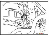
3. Remove differential side oil seals (1) from clutch housing and transaxle case, using an oil seal remover.
CAUTION:
Never damage transaxle case and clutch housing.
INSTALLATION
Note the following, and install in the reverse order of removal.
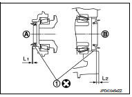
• Install differential side oil seals (1) to clutch housing and transaxle case, using the drift [Stamping number: B.vi 1666-B] of the drift set [SST: KV32500QAA].
A : Transaxle case side B : Clutch housing side
Dimension “L1” : 1.2 – 1.8 mm (0.047 – 0.071 in) Dimension “L2” : 2.7 – 3.3 mm (0.106 – 0.130 in)
CAUTION:
• Never incline differential side oil seal.
• Never damage clutch housing and transaxle case.
Inspection
INSPECTION AFTER INSTALLATION
Check the oil level and oil leakage. Refer to TM-75, "Inspection".

 Position switch
Removal and Installation
REMOVAL
1. Remove air cleaner case. (K9K) Refer to EM-280, "Removal and
Installation".
2. Remove battery. (MR16DDT) Refer to PG-124, "Removal and Installat ...
Other materials:
Air breather hose
Removal and Installation
REMOVAL
1. Remove clip from bracket.
2. Remove air breather hose from transaxle assembly.
INSTALLATION
Note the following, and install in the reverse order of removal.
CAUTION:
• Check that air breather hose is not collapsed or blocked due to folding or
bendin ...
C1140 actuator relay system
DTC Logic
DTC DETECTION LOGIC
DTC CONFIRMATION PROCEDURE
1.PRECONDITIONING
If “DTC CONFIRMATION PROCEDURE” has been previously conducted, always turn
ignition switch OFF and
wait at least 10 seconds before conducting the next test.
>> GO TO 2.
2.CHECK DTC DETECTION
With CON ...
P0222, P0223 TP sensor
DTC Logic
DTC DETECTION LOGIC
NOTE:
If DTC P0222 or P0223 is displayed with DTC P0643, first perform the trouble
diagnosis for DTC P0643.
Refer to EC-686, "DTC Logic".
DTC CONFIRMATION PROCEDURE
1.PRECONDITIONING
If DTC Confirmation Procedure has been previously conducted, alw ...
