Nissan Juke Service and Repair Manual : Removal and Installation Procedure for CVT Unit Connector
REMOVAL
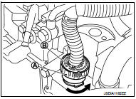
• Rotate bayonet ring (A) counterclockwise. Pull out CVT unit harness connector (B) upward and remove it.
INSTALLATION
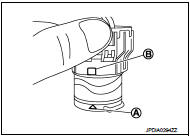
1. Align marking (A) on CVT unit harness connector terminal with marking (B) on bayonet ring. Insert CVT unit harness connector.
2. Rotate bayonet ring clockwise.
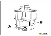
3. Rotate bayonet ring clockwise until marking (A) on CVT unit harness connector terminal body is aligned with the slit (B) on bayonet ring as shown in the figure (correctly fitting condition).
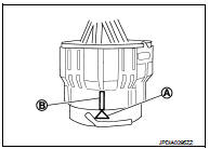
CAUTION:
• Securely align marking (A) on CVT unit harness connector
terminal body with bayonet ring slit (B). Then, be careful
not to make a half fit condition as shown in the figure.
• Never mistake the slit of bayonet ring for other dent portion.
 On Board Diagnosis (OBD) System of CVT and Engine
The ECM has an on board diagnostic system. It will light up the malfunction
indicator lamp (MIL) to warn the
driver of a malfunction causing emission deterioration.
CAUTION:
• Be sure to turn ...
 Preparation
...
Other materials:
System
System Description
• The system switches fluid pressure of each brake caliper to increase, to
hold or to decrease according to
signals from control unit in ABS actuator and electric unit (control unit). This
control system is applied to ABS
function and EBD function.
• Fail-safe function ...
Measurement of weights
Secure loose items to prevent weight shifts that could affect the balance of
your vehicle. When the vehicle is loaded, drive to a scale and weigh the front and
the rear wheels separately to determine axle loads.
Individual axle loads should not exceed either of the Gross Axle Weight Ratings
( ...
Timing chain
Exploded View
1. Timing chain slack guide
2. Timing chain tensioner
3. Timing chain
4. Oil pump drive chain
5. Crankshaft sprocket
6. Crankshaft key
7. Oil pump sprocket
8. Front cover
9. O-ring
10. O-ring
11. Oil control valve cover
12. O-ring
13. Oil control valve (EXH)
14 ...
