Nissan Juke Service and Repair Manual : Removal and installation
COMBINATION METER
Exploded View
REMOVAL
Refer to IP-12, "Exploded View".
DISASSEMBLY
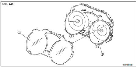
1. Front cover
2. Unified meter control unit
Removal and Installation
REMOVAL
1. Remove cluster lid A. Refer to IP-13, "Removal and Installation".
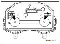
2. Remove the mounting screws of the combination meter.
3. Pull the combination meter straight to disengage resin clips.
(The figure shows the clip positions on the back of the combination
meter.)
CAUTION:
Never damage the front cover.
4. Turn the lower part of the combination meter in the direction of the arrow to remove the combination meter from the instrument panel assembly.
CAUTION:
Never damage the front cover.
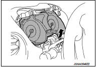
5. Remove connector to remove the combination meter.
CAUTION:
Never damage the front cover.
INSTALLATION
Install in the reverse order of removal.
Disassembly and Assembly
DISASSEMBLY
1. Disengage the pawls (2 on the sides, 3 on the lower part) of the combination meter.
2. Insert the removal tool into the clearance (in the order of A, B) between the front cover and the meter control unit. Remove 4 pawls on the upper side of the front cover by turning the tool while increasing the clearance.
CAUTION:
Wrap the removal tools with protective tape to prevent
scratches.
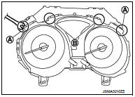
3. Pull the front cover straight to remove it from the meter control unit assembly.
CAUTION:
Never damage the front cover.
Never touch the pointer and the crystalline liquid.
ASSEMBLY
Install the front cover straight to the meter control unit assembly and engage all the pawl.
CAUTION:
Never damage the front cover.
 Normal operating condition
INFORMATION DISPLAY
INFORMATION DISPLAY : Description
AMBIENT TEMPERATURE
The displayed ambient temperature on the information display may differ from
the actual temperature because
it is a corr ...

Other materials:
Periodic maintenance
STEERING WHEEL
Inspection
STEERING WHEEL AXIAL END PLAY
1. Check installation conditions of steering gear assembly, front suspension
assembly, axle and steering column
assembly.
2. Check if movement exists when steering wheel is moved up and down, to the
left and right and to the axial
dir ...
Both side headlamps (HI) are not turned on
Description
Both side headlamps (HI) are not turned ON when setting to the lighting
switch HI or PASS.
Diagnosis Procedure
1.COMBINATION SWITCH INSPECTION
Check the combination switch. Refer to BCS-92, "Symptom Table".
Is the inspection result normal?
YES >> GO TO 2.
NO ...
Headlight switch
Lighting
1 Turn the switch to the position:
The front parking, side marker, tail, license plate, instrument lights and daytime
running lights (for NISMO models) will come on.
2 Turn the switch to the position:
Headlights will come on and all the other lights remain on. However, the daytime ...
