Nissan Juke Service and Repair Manual : Removal and installation
REAR WHEEL HUB
Exploded View
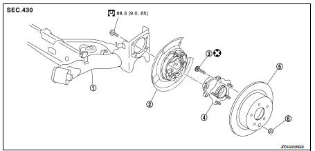
1. Rear suspension beam
2. Rear brake assembly
3. Hub bolt
4. Wheel hub assembly (Bearing-integrated
type)
5. Disc rotor
6. Plug
 : Always replace after every
disassembly.
 : N·m (kg-m, ft-lb)
Removal and Installation
REMOVAL
1. Remove tires. Refer to WT-7, "Removal and Installation".
2. Remove wheel sensor. Refer to BRC-86, "REAR WHEEL SENSOR : Removal and Installation" (Without ESP), BRC-227, "REAR WHEEL SENSOR : Removal and Installation" (With ESP).
3. Remove caliper assembly. Hang caliper assembly in a place where it will not interfere with work. Refer to BR-65, "BRAKE CALIPER ASSEMBLY : Removal and Installation" (LHD), BR-131, "BRAKE CALIPER ASSEMBLY : Removal and Installation" (RHD).
CAUTION:
Never depress brake pedal while brake caliper is removed.
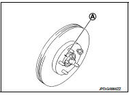
4. Remove disc rotor. If disc rotor cannot be removed, remove as follows.
CAUTION:
• Parking brake completely in the released position.
• Put matching marks (A) on the wheel hub assembly and the disc rotor before removing the disc rotor.
• Never drop disc rotor.
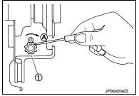
a. Fix the disc rotor with wheel nuts and remove the adjusting hole plug.
b. Using suitable tool, rotate adjuster (1) in the direction (A) to retract and loosen brake shoe.
5. Remove wheel hub assembly.
6. Remove hub bolts from wheel hub assembly, using a press.
CAUTION:
• Remove hub bolt only when necessary.
• Never hammer the hub bolt to avoid impact to the wheel hub assembly.
• Pull out the hub bolt in a direction perpendicular to the wheel hub assembly.
7. Perform inspection after removal. Refer to RAX-6, "Inspection".
INSTALLATION
Note the following, and install in the reverse order of removal.
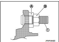
• Place a washer (A) as shown in the figure to install the hub bolts (1) by using the tightening force of the nut (B).
CAUTION:
• Check that there is no clearance between wheel hub assembly
and hub bolt.
• Never reuse hub bolt.
• Align the matching marks that have been made during removal when reusing the disc rotor.
• Perform inspection after installation. Refer to RAX-6, "Inspection".
Inspection
INSPECTION AFTER REMOVAL
Check the wheel hub assembly for wear, cracks, and damage. Replace if necessary.
INSPECTION AFTER INSTALLATION
1. Check wheel sensor harness for proper connection. BRC-85, "REAR WHEEL SENSOR : Exploded View" (Without ESP), BRC-225, "REAR WHEEL SENSOR : Exploded View" (With ESP).
2. Adjust parking brake operation (stroke). Refer to PB-2, "Inspection and Adjustment".
3. Check wheel alignment. Refer to RSU-20, "Inspection".
 Periodic maintenance
REAR WHEEL HUB
Inspection
COMPONENT PART
Check the mounting conditions (looseness, back lash) of each component and
component conditions (wear,
damage) are normal.
WHEEL HUB ASSEMBLY (BEARING ...
 Service data and specifications (SDS)
Wheel Bearing
...
Other materials:
Wiring diagram
DOOR & LOCK SYSTEM
Wiring Diagram
For connector terminal arrangements, harness layouts, and alphabets in a
(option abbreviation; if not
described in wiring diagram), refer to GI-12, "Connector Information/Explanation
of Option Abbreviation".
...
Map light control switch (if so equipped)
The map lights control switch has three positions: ON1 , OFF2 and center.
ON position
When the switch is in the ON position 1 , the map lights will illuminate.
OFF position
When the switch is in the OFF position2 , the map lights will not illuminate,
regardless of the condition.
Center posi ...
Security systems
To provide comprehensive protection, your Nissan Leaf is equipped with two distinct security systems designed to safeguard your vehicle:
Vehicle security system
NISSAN Vehicle Immobilizer System
The current operational status of these systems ...
