Nissan Juke Service and Repair Manual : Rear disc brake
Brake pad : Inspection and Adj
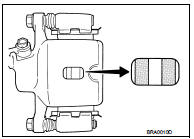
INSPECTION
Check brake pad wear thickness from an inspection hole on cylinder body. Check using a scale if necessary.
Wear thickness : Refer to BR-137, "Rear Disc Brake".
ADJUSTMENT
Burnish contact surfaces between disc rotor and brake pads according to the following procedure after refinishing or replacing brake pads, or if a soft pedal occurs at very low mileage.
CAUTION:
ŌĆó Be careful of vehicle speed because the brake does not operate firmly/securely
until pads and disc
rotor are securely fitted.
ŌĆó Only perform this procedure under safe road and traffic conditions. Use extreme caution.
1. Drive vehicle on straight, flat road.
2. Depress brake pedal with the power to stop vehicle within 3 to 5 seconds until the vehicle stops.
3. Drive without depressing brake for a few minutes to cool the brake.
4. Repeat steps 1 to 3 until pad and disc rotor are securely fitted.
Disc rotor : Inspection and Adjustment
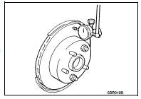
INSPECTION
Appearance
Check surface of disc rotor for uneven wear, cracks, and serious damage. Replace
it if necessary.
ŌĆó 2WD: Refer to RAX-5, "Removal and Installation".
ŌĆó 4WD: Refer to RAX-14, "Removal and Installation".
Runout
1. Fix the disc rotor to the wheel hub and bearing assembly with
wheel nuts (2 points at least).
2. Check the wheel bearing axial end play before the inspection.
ŌĆó 2WD: Refer to RAX-4, "Inspection".
ŌĆó 4WD: Refer to RAX-12, "Inspection".
3. Inspect the runout with a dial indicator to measure at 10 mm (0.39 in) inside the disc edge.
Runout (with it attached to the vehicle) : Refer to BR-137, "Rear Disc Brake".
4. Find the installation position that has a minimum runout by shifting the disc rotor-to-wheel hub and bearing assembly installation position by one hole at a time if the runout exceeds the limit value.
ŌĆó Refinish the disc rotor if the runout is outside the limit even after performing the above operation.
CAUTION:
ŌĆó Check in advance that the thickness of the disc rotor is wear thickness + 0.3
mm (0.012 in) or more.
ŌĆó If the thickness is less than wear thickness + 0.3 mm (0.012 in), replace the disc rotor.
- 2WD: Refer to RAX-5, "Removal and Installation".
- 4WD: Refer to RAX-14, "Removal and Installation".
Wear thickness : Refer to BR-137, "Rear Disc Brake".
Thickness
Check the thickness of the disc rotor using a micrometer. Replace
the disc rotor if the thickness is below the wear limit.
ŌĆó 2WD: Refer to RAX-5, "Removal and Installation".
ŌĆó 4WD: Refer to RAX-14, "Removal and Installation".
Wear thickness : Refer to BR-137, "Rear Disc Brake".
ADJUSTMENT
Burnish contact surfaces between disc rotors and brake pads according to the following procedure after refinishing or replacing disc rotor, or if a soft pedal occurs at very low mileage.
CAUTION:
ŌĆó Be careful of vehicle speed because the brake does not operate firmly/securely
until pad and disc
rotor are securely fitted.
ŌĆó Only perform this procedure under safe road and traffic conditions. Use extreme caution.
1. Drive vehicle on straight, flat road.
2. Depress brake pedal with the power to stop vehicle within 3 to 5 seconds until the vehicle stops.
3. Drive without depressing brake for a few minutes to cool the brake.
4. Repeat steps 1 to 3 until pad and disc rotor are securely fitted.
 Front disc brake
Brake pad : Inspection and Adjustment
INSPECTION
Check brake pad wear thickness from an inspection hole on cylinder
body. Check using a scale if necessary.Wear thickness : Refer to BR-137, "Fr ...

Other materials:
P0420 three way catalyst function
DTC Logic
DTC DETECTION LOGIC
The ECM monitors the switching frequency ratio of air fuel ratio (A/F)
sensor 1 and heated oxygen sensor 2.
A three way catalyst (manifold) with high oxygen storage capacity
will indicate a low switching frequency of heated oxygen sensor 2.
As oxygen storage c ...
B terminal circuit
Description
The ŌĆ£BŌĆØ terminal is constantly supplied with battery power.
Diagnosis Procedure
CAUTION:
Perform diagnosis under the condition that engine cannot start by the following
procedure.
1. Remove fuel pump fuse.
2. Crank or start the engine (where possible) until the fuel pressur ...
Fuel Efficient Driving Tips
Follow these easy-to-use Fuel Efficient Driving Tips to help you achieve the
most fuel economy from your vehicle.
1. Use smooth accelerator and brake pedal application.
ŌĆó Avoid rapid starts and stops.
ŌĆó Use smooth, gentle accelerator and brake application whenever possible.
ŌĆó ...
