Nissan Juke Service and Repair Manual : Fillet molding
Exploded View
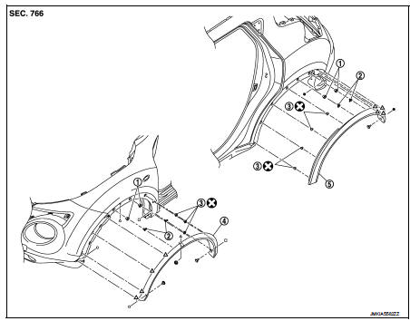
1. Grommet
2. Clip
3. Clip
4. Front fillet molding
5. Rear fillet molding
 : Pawl
 : Do not reuse
Front fillet molding
FRONT FILLET MOLDING : Removal and Installation
REMOVAL
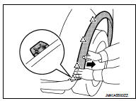
1. Remove front fillet molding fixing clips.
2. Remove front fillet molding front side fixing pawls.
 : Pawl
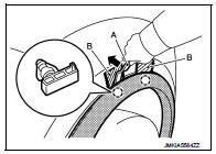
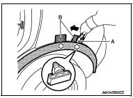
3. Using remover tool (A), disengage the clips from front fillet molding by starting from front side.
 : Clip
CAUTION:
• Apply a protective tape (B) on the body to protect the
painted surface from damage.
• Never pull fillet molding strongly.
INSTALLATION
Note the following items, and then install in the reverse order of removal.
CAUTION:
• Always replace fillet molding fixing clips.
• When installing front fillet molding, check that blind clips and pawls are securely fitted in panel holes on body, and then press them in.
Rear fillet molding
REAR FILLET MOLDING : Removal and Installation
REMOVAL
1. Remove filet molding fixing clip from end of sill cover.
2. Remove rear fillet molding rear side fixing pawls.
 : Pawl
CAUTION:
Never pull the rear fillet molding strongly.
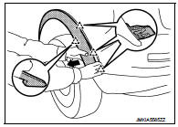
3. Using remover tool (A), disengage the clips from rear fillet molding by starting from rear side.
 : Clip
CAUTION:
• Apply a protective tape (B) on the body to protect the
painted surface from damage.
• Never pull the rear fillet molding strongly.
INSTALLATION
Note the following items, and then install in the reverse order of removal.
CAUTION:
• Always replace fillet molding fixing clips.
• When installing rear fillet molding, check that blind clips and pawls are securely fitted in panel holes on body, and then press them in.
 Floor side fairing
Exploded View
1. Push spring nut
2. Floor under cover RH
3. Floor under cover LH
Removal and Installation
REMOVAL
FLOOR UNDER COVER
Remove floor under cover mounting nut and push spring nut ...
 Roof side molding
Exploded View
1. Roof side molding
2. Roof side molding clip
3. Double-sided tape [t: 2.5 mm (0.098 in)]
4. Body side outer panel
5. Roof panel
: Vehicle front
: Do not reuse
Removal and ...
Other materials:
Engine maintenance (MR16DDT)
Drive belt
DRIVE BELT : Exploded View
1. Alternator
2. Drive belt auto-tensioner
3. Crankshaft pulley
4. A/C compressor
5. Water pump
6. Drive belt
A. Possible use range
B.
Range when new drive belt is installed
C. Indicator
DRIVE BELT : Checking
WARNING:
Perform this step when ...
Windows
POWER WINDOWS
WARNING
• Make sure that all passengers have their hands, etc. inside the vehicle
while it is in motion and before closing the windows. Use the window lock switch
to prevent unexpected use of the power windows.
• Do not leave children unattended inside the vehicle. They coul ...
Cleaning interior
Occasionally remove loose dust from the interior trim, plastic parts and seats
using a vacuum cleaner or soft bristled brush. Wipe the vinyl and leather surfaces
with a clean, soft cloth dampened in mild soap solution, then wipe clean with a
dry soft cloth.
Regular care and cleaning is requir ...
