Nissan Juke Service and Repair Manual : A/C indicator
Diagnosis Procedure
1.CHECK SYMPTOM
Check symptom.
A/C indicator dose not turn ON>>GO TO 2.
A/C indicator dose not turn OFF>>GO TO 6.
2.CHECK FUSE
1. Turn ignition switch OFF.
2. Check 10A fuse (No. 15, located in fuse block (J/B)].
NOTE
:
Refer to PG-22, "Fuse, Connector and Terminal Arrangement".
Is the inspection result normal? YES >> GO TO 3.
NO >> Replace the blown fuse after repairing the affected circuit if a fuse is blown.
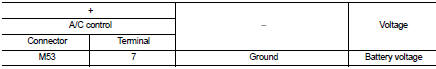
3.CHECK A/C INDICATOR POWER SUPPLY
1. Turn ignition switch ON.
2. Check voltage between A/C control harness connector and ground.
Is the inspection result normal? YES >> GO TO 4.
NO >> Repair harness or connector between A/C control and fuse.
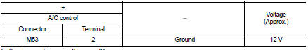
4.CHECK A/C INDICATOR CIRCUIT
Check voltage between A/C control harness connector and ground.
Is the inspection result normal? YES >> GO TO 5.
NO >> Replace A/C control. Refer to HAC-304, "Removal and Installation".
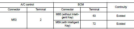
5.CHECK A/C INDICATOR CIRCUIT FOR OPEN
1. Turn ignition switch OFF.
2. Disconnect A/C control connector and BCM connector.
3. Check continuity between A/C control harness connector and BCM harness connector.
Is the inspection result normal? YES >> Replace BCM. Refer to BCS-93, "Removal and Installation" (with Intelligent Key) or BCS-161, "Removal and Installation" (without Intelligent Key).
NO >> Repair harness or connector.
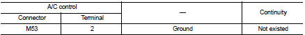
6.CHECK A/C INDICATOR CIRCUIT FOR SHORT
1. Turn ignition switch OFF.
2. Disconnect A/C control connector and BCM connector.
3. Check continuity between A/C control harness connector and ground.
Is the inspection result normal? YES >> Replace BCM. Refer to BCS-93, "Removal and Installation" (with Intelligent Key) or BCS-161, "Removal and Installation" (without Intelligent Key).
NO >> Repair harness or connector.
 Thermo control amplifier
Component Function Check
1.CHECK A/C ON SIGNAL
With CONSULT-III
1. Turn ignition switch ON.
2. Select ÔÇťAIR CONDITIONERÔÇŁ of ÔÇťBCMÔÇŁ using CONSULT-III.
3. Select ÔÇťTHERMO AMPÔÇŁ in ÔÇťDATA M ...
 Blower motor
Diagnosis Procedure
1.CHECK SYMPTOM
Check symptom (A or B).
Which symptom is detected?
A >> GO TO 2.
B >> GO TO 7.
2.CHECK FUSE
1. Turn ignition switch OFF.
2. Check 15A fuse ...
Other materials:
Intelligent key warning buzzer
Component Function Check
1.CHECK FUNCTION
1. Select ÔÇťINTELLIGENT KEYÔÇŁ of ÔÇťBCMÔÇŁ using CONSULT-III.
2. Select ÔÇťOUTSIDE BUZZERÔÇŁ in ÔÇťACTIVE TESTÔÇŁ mode.
3. Check that the function operates normally according to the following
conditions.
Is the inspection result normal?
YES >& ...
Steering gear and linkage
Exploded View
REMOVAL
LHD Models
1. Steering gear assembly
2. Heat insulator
3. Front suspension member
: Vehicle front
: Always replace after every
disassembly.
: N┬Ěm (kg-m, ft-lb)
: N┬Ěm (kg-m, in-lb)
RHD Models
1. Steering gear assembly
2. Heat insulator
3. Front suspensio ...
Front door
Exploded View
1. Front door panel
2. Grommet
3. Door hinge (upper)
4. Door hinge (lower)
5. Door check link
6. Bumper rubber
7. Door pad
8. Door striker
9. TORX bolt
10. Grommet
: Do not reuse
: N┬Ěm (kg-m, in-lb)
: N┬Ěm (kg-m, ft-lb)
: Body grease
Door assembly
DOOR ASSEMBLY ...
