Nissan Juke Service and Repair Manual : Parking, license plate and tail lamps are not turned on
Without daytime running light system
WITHOUT DAYTIME RUNNING LIGHT SYSTEM : Description
The parking, license plate, tail lamps and each illumination are not turned ON in any condition.
WITHOUT DAYTIME RUNNING LIGHT SYSTEM : Diagnosis Procedure
1.COMBINATION SWITCH INSPECTION
Check the combination switch. Refer to BCS-92, "Symptom Table".
Is the inspection result normal? YES >> GO TO 2.
NO >> Repair or replace the malfunctioning part.
2.CHECK TAIL LAMP RELAY REQUEST SIGNAL INPUT
 CONSULT-III DATA MONITOR
1. Select ÔÇťTAIL & CLR REQÔÇŁ of IPDM E/R data monitor item.
2. With operating the lighting switch, check the monitor status.
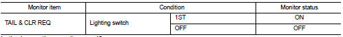
Is the inspection result normal? YES >> Replace IPDM E/R.
NO >> Replace BCM. Refer to BCS-93, "Removal and Installation" (with Intelligent Key), BCS-161, "Removal and Installation" (without Intelligent Key).
With daytime running light system
WITH DAYTIME RUNNING LIGHT SYSTEM : Description
The parking, license plate, tail lamps and each illumination are not turned ON in any condition.
WITH DAYTIME RUNNING LIGHT SYSTEM : Diagnosis Procedure
1.COMBINATION SWITCH INSPECTION
Check combination switch. Refer to BCS-92, "Symptom Table".
Is the combination switch normal? YES >> GO TO 2.
NO >> Repair or replace the malfunctioning part.
2.CHECK TAIL LAMP RELAY REQUEST SIGNAL INPUT
 CONSULT-III DATA MONITOR
1. Select ÔÇťTAIL & CLR REQÔÇŁ of IPDM E/R data monitor item.
2. With operating the lighting switch, check the monitor status
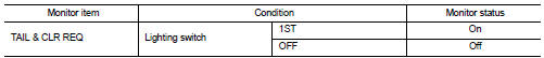
Is the inspection result normal? YES >> GO TO 3.
NO >> Replace BCM. Refer to BCS-93, "Removal and Installation" (with Intelligent Key), BCS-161, "Removal and Installation" (without Intelligent Key).
3.DAYTIME RUNNING LIGHT RELAY CIRCUIT INSPECTION
Check the daytime running light relay circuit. Refer to EXL-50, "Component Function Check".
Is the inspection result normal? YES >> Replace IPDM E/R.
NO >> Repair or replace the malfunctioning part.
 Both side headlamps (LO) are not turned on
Description
Both side headlamps (LO) are not turned ON in any condition.
Diagnosis Procedure
1.CHECK COMBINATION SWITCH
Check the combination switch. Refer to BCS-92, "Symptom Table".
...
 Both side front fog lamps are not turned on
Description
The front fog lamps are not turned ON in any condition.
Diagnosis Procedure
1.CHECK FUSE
Check that the following fuse is fusing.
Is the inspection result normal?
YES >> GO T ...
Other materials:
P1611 ID discord, IMMU-ECM
DTC Logic
DTC DETECTION LOGIC
DTC CONFIRMATION PROCEDURE
1.PERFORM DTC CONFIRMATION PROCEDURE
1. Turn ignition switch ON.
2. Check DTC in ÔÇťSelf Diagnostic ResultÔÇŁ mode of ÔÇťENGINEÔÇŁ using CONSULT-III.
Is DTC detected?
YES >> Refer to SEC-193, "Diagnosis Procedure".
...
Light & rain sensor
Component Function Check
1.CHECK FRONT WIPER AUTO OPERATION
1. Clean rain sensor detection area of windshield fully.
2. When the front wiper switch is turned to AUTO position, front wiper operates
once regardless of a rainy
condition.
Is front wiper (AUTO) operation normally?
YES >> ...
Hazard function
Component Function Check
1.CHECK FUNCTION
1. Select ÔÇťMULTI REMOTE ENTÔÇŁ of ÔÇťBCMÔÇŁ using CONSULT-III.
2. Select ÔÇťFLASHERÔÇŁ in ÔÇťACTIVE TESTÔÇŁ mode.
3. Check that the function operates normally according to the following
conditions.
Is the inspection result normal?
YES >> Ha ...
