Nissan Juke Service and Repair Manual : P2100 electric throttle control function
DTC Logic
DTC DETECTION LOGIC
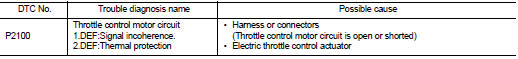
Diagnosis Procedure
1.CHECK GROUND CONNECTION
1. Turn ignition switch OFF and wait at least 4 minutes.
2. Check ground connection E38. Refer to Ground inspection in GI-44, "Circuit Inspection".
Is the inspection result normal? YES >> GO TO 2.
NO >> Repair or replace ground connection.
2.CHECK THROTTLE CONTROL MOTOR CIRCUIT FOR OPEN AND SHORT
1. Disconnect electric throttle control actuator harness connector.
2. Disconnect ECM harness connectors.
3. Check the continuity between the following terminals.
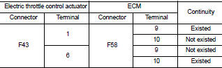
4. Also check harness for short to ground and short to power.
Is the inspection result normal? YES >> GO TO 3.
NO >> Repair open circuit, short to ground or short to power in harness or connectors.
3.CHECK THROTRTLE CONTROL MOTOR
Perform EC-998, "Component Inspection".
Is the inspection result normal? YES >> GO TO 5.
NO >> GO TO 4.
4.REPLACE ELECTRIC THROTTLE CONTROL ACTUATOR
1. Replace electric throttle control actuator.
2. Perform EC-998, "Special Repair Requirement".
>> INSPECTION END
5.CHECK INTERMITTENT INCIDENT
Refer to GI-42, "Intermittent Incident".
>> INSPECTION END
Component Inspection
1.CHECK THROTTLE CONTROL MOTOR
1. Reconnect all harness connectors disconnected.
2. Check the voltage between ECM harness connectors terminals under the following conditions.
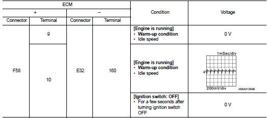
Is the inspection result normal? YES >> INSPECTION END
NO >> GO TO 2.
2.REPLACE ELECTRIC THROTTLE CONTROL ACTUATOR
1. Replace electric throttle control actuator.
2. Perform EC-998, "Special Repair Requirement".
>> INSPECTION END
Special Repair Requirement
1.PERFORM THROTTLE VALVE CLOSED POSITION LEARNING
Refer to EC-882, "Work Procedure".
>> END
 P2080 EGT sensor 1
DTC Logic
DTC DETECTION LOGIC
Diagnosis Procedure
1.CHECK GROUND CONNECTIONS
1. Turn ignition switch OFF.
2. Check ground connection E38. Refer to Ground inspection in GI-44, "Circuit
In ...
 P2119 electric throttle control function
DTC Logic
DTC DETECTION LOGIC
Diagnosis Procedure
1.CHECK INTERMITTENT INCIDENT
Refer to GI-42, "Intermittent Incident".
Is the inspection result normal?
YES >> GO TO 2.
N ...
Other materials:
Final drive
Exploded View
1. Shim
2. Differential side bearing outer race
(transaxle case side)
3. Differential side bearing inner race
(transaxle case side)
4. Final gear
5. Differential case
6. Differential side bearing inner race
(clutch housing side)
7. Differential side bearing outer race
( ...
When traveling or registering your vehicle in another country
When planning to travel in another country, you should first find out if the
fuel available is suitable for your vehicleŌĆÖs engine.
Using fuel with an octane rating that is too low may cause engine damage. All
gasoline vehicles must be operated with unleaded gasoline.
Therefore, avoid taking ...
Front wiper auto stop signal circuit
Component Function Check
1.CHECK FRONT WIPER (AUTO STOP) SIGNAL
CONSULT-III DATA MONITOR
1. Select ŌĆ£WIP AUTO STOPŌĆØ of IPDM E/R data monitor item.
2. Operate the front wiper.
3. With the front wiper operation, check the monitor status.
Is the status of item normal?
YES >> Auto stop ...
