Nissan Juke Service and Repair Manual : Components
• THE LARGE ILLUSTRATIONS
are exploded views (see the following) and contain tightening torques, lubrication points, section number of the PARTS CATALOG (e.g. SEC. 440) and other information necessary to perform repairs.
The illustrations should be used in reference to service matters only. When ordering parts, refer to the appropriate PARTS CATALOG.
Components shown in an illustration may be identified by a circled number. When this style of illustration is used, the text description of the components will follow the illustration.
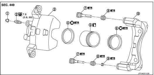
1. Cap
2. Bleeder valve
3. Cylinder body
4. Piston seal
5. Piston
6. Piston boot
7. Sliding pin
8. Sliding pin boot
9. Bushing
10. Torque member
 : Apply rubber grease.
 : Apply brake fluid.
 : N·m (kg-m, in-lb)
 : Always replace after every
disassembly
SYMBOLS
 Relation between Illustrations and Descriptions
The following sample explains the relationship between the part description
in an illustration, the part name in
the text and the service procedures.
...

Other materials:
P0327, P0328 KS
DTC Logic
DTC DETECTION LOGIC
DTC CONFIRMATION PROCEDURE
1.PRECONDITIONING
If DTC Confirmation Procedure has been previously conducted, always turn
ignition switch OFF and wait at
least 10 seconds before conducting the next test.
TESTING CONDITION:
Before performing the following proced ...
B1074, B1075, B1076, B1077, B1078, B1079 diagnosis sensor unit
DTC Logic
DTC DETECTION LOGIC
DTC CONFIRMATION PROCEDURE
1.CHECK SELF-DIAG RESULT
With CONSULT-III
1. Turn ignition switch ON.
2. Perform “Self Diagnostic Result” mode of “AIR BAG” using CONSULT-III.
Without CONSULT-III
1. Turn ignition switch ON.
2. Check the air bag warning la ...
Precaution Necessary for Steering Wheel Rotation after Battery Disconnect
NOTE:
• Before removing and installing any control units, first turn the ignition
switch to the LOCK position, then disconnect
both battery cables.
• After finishing work, confirm that all control unit connectors are connected
properly, then re-connect both
battery cables.
• Always us ...
