Nissan Juke Service and Repair Manual : U1000 can comm circuit
Description
CAN (Controller Area Network) is a serial communication line for real time application. It is an on-vehicle multiplex communication line with high data communication speed and excellent error detection ability. Many electronic control units are equipped onto a vehicle, and each control unit shares information and links with other control units during operation (not independent). In CAN communication, control units are connected with 2 communication lines (CAN-H line, CAN-L line) allowing a high rate of information transmission with less wiring.
Each control unit communicate data but selectively reads required data only.
DTC Logic
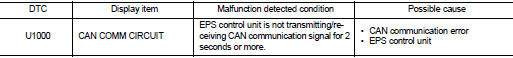
DTC DETECTION LOGIC
DTC CONFIRMATION PROCEDURE
1.PRECONDITIONING
If “DTC CONFIRMATION PROCEDURE” has been previously conducted, always turn ignition switch OFF and wait at least 10 seconds before conducting the next test.
>> GO TO 2.
2.DTC REPRODUCTION PROCEDURE
 With CONSULT-III
1. Turn the ignition switch OFF to ON.
2. Perform “EPS” self-diagnosis.
Is DTC “U1000” detected? YES >> Proceed to diagnosis procedure. Refer to STC-25, "Diagnosis Procedure".
NO >> INSPECTION END
Diagnosis Procedure
Proceed to LAN-17, "Trouble Diagnosis Flow Chart".
 C1609 vehicle speed signal
DTC Logic
DTC DETECTION LOGIC
DTC CONFIRMATION PROCEDURE
1.PRECONDITIONING
If “DTC CONFIRMATION PROCEDURE” has been previously conducted, always turn
ignition switch OFF and
wait at least ...
 EPS warning lamp
Component Function Check
1.CHECK THE ILLUMINATION OF THE EPS WARNING LAMP
Check that the EPS warning lamp turns ON when ignition switch turns ON. Then,
EPS warning lamp turns
OFF after the engine ...
Other materials:
Clutch disc and clutch cover
Except for K9K : Exploded View
HR16DE
1. Flywheel
2. Clutch disc
3. Clutch cover
4. Input shaft
A. First step
B. Final step
: N·m (kg-m, ft-lb)
: Apply lithium-based grease
including molybdenum disulphide.
MR16DDT
1. Flywheel
2. Clutch disc
3. Clutch cover
4. Input shaft
A ...
Safety note
WARNING
• Do not disassemble or modify this system. If you do, it may result in accidents,
fire, or electric shock.
• Do not use this system if you notice any abnormality, such as a frozen screen
or lack of sound. Continued use of the system may result in accident, fire or electric
shock ...
Cooling fan
Exploded View
1. Fan motor
2. Fan shroud
3. Cooling fan
A. Apply on fan motor shaft
: N·m (kg-m, in-lb)
: Apply genuine high strength thread
locking sealant or equivalent.
Removal and Installation
REMOVAL
1. Drain engine coolant. Refer to CO-11, "Draining".
CAUTION:
• ...
