Nissan Juke Service and Repair Manual : P1651 starter motor relay
Description
ECM controls ON/OFF state of the starter relay, according to the engine and vehicle condition. Models with no Intelligent Key System transmit a control signal directly to IPDM E/R. On the other hand, models with the Intelligent Key System transmit a control signal to IPDM E/R by way of BCM via CAN communication.
Under normal conditions, ECM controls and maintains the starter relay in OFF state during engine running or “D” position.
When detecting a decrease in engine speed due to rapid deceleration or heavy load condition, ECM controls and reactivates the starter relay.
IPDM E/R detects a control state of starter relay and starter control relay and transmits a feedback signal to ECM via CAN communication.
DTC Logic
DTC DETECTION LOGIC
NOTE
:
• If DTC P1650 is displayed with DTC U1001, perform the trouble diagnosis for
DTC U1001. Refer to EC-161,
"DTC Logic".
• If DTC P1650 is displayed with DTC P0607, perform the trouble diagnosis for DTC P0607. Refer to EC-304, "DTC Logic".
• If DTC P1650 is displayed with B209F or B20A0 of IPDM E/R, perform the trouble diagnosis for B209F or B20A0. Refer to SEC-134, "DTC Logic" or SEC-136, "DTC Logic".
• If DTC P1650 is displayed with B26F9 or B26FA of BCM, perform the trouble diagnosis for B209F or B20A0.
Refer to SEC-128, "DTC Logic" or SEC-130, "DTC Logic"

DTC CONFIRMATION PROCEDURE
1.PRECONDITIONING
If DTC Confirmation Procedure has been previously conducted, always perform the following procedure before conducting the next test.
1. Turn ignition switch OFF and wait at least 10 seconds.
2. Turn ignition switch ON.
3. Turn ignition switch OFF and wait at least 10 seconds.
>> GO TO 2.
2.PERFORM DTC CONFIRMATION PROCEDURE FOR MALFUNCTION
1. Turn ignition switch OFF and wait at least 10 seconds.
2. Start the engine and let it idle at least 30 seconds.
3. Check 1st trip DTC.
Is 1st trip DTC detected? YES >> Proceed to EC-370, "Diagnosis Procedure".
NO >> INSPECTION END
Diagnosis Procedure
1.INSPECTION START
Check the starter motor operation.
Is the starter motor operated? YES >> GO TO 3.
NO >> GO TO 2.
2.CHECK DTC WITH IPDM E/R
Check DTC with IPDM E/R. Refer to PCS-14, "CONSULT-III Function (IPDM E/R)".
Is the inspection result normal? YES-1 >> With Intelligent Key system: GO TO 3.
YES-2 >> Without Intelligent Key system: GO TO 6.
NO >> Perform trouble diagnosis for DTC indicated.
3.CHECK DTC WITH BCM
Check DTC with BCM. Refer to BCS-36, "BCM : CONSULT-III Function (BCM - BCM)".
Is the inspection result normal? YES >> GO TO 4.
NO >> Perform trouble diagnosis for DTC indicated.
4.CHECK CRANKING REQUEST SIGNAL CIRCUIT-I
1. Turn ignition switch OFF.
2. Disconnect ECM harness connector.
3. Disconnect IPDM E/R harness connector.
4. Check the continuity between ECM harness connector and IPDM E/R harness connector.
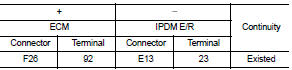
5. Also check harness for short to ground to power.
Is the inspection result normal? YES >> GO TO 5.
NO >> Repair or replace error-detected parts.
5.CHECK CRANKING REQUEST SIGNAL CIRCUIT-II
1. Disconnect BCM harness connector.
2. Check the continuity between ECM harness connector and BCM harness connector.
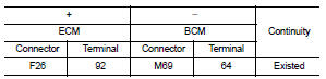
3. Also check harness for short to ground to power.
Is the inspection result normal? YES >> GO TO 7.
NO >> Repair or replace error-detected parts.
6.CHECK CRANKING REQUEST SIGNAL CIRCUIT-III
1. Turn ignition switch OFF.
2. Disconnect ECM harness connector.
3. Disconnect IPDM E/R harness connector.
4. Check the continuity between ECM harness connector and IPDM E/R harness connector.
 P1650 starter motor relay 2
Description
ECM controls ON/OFF state of the starter relay, according to the engine and
vehicle condition. Models with no
Intelligent Key System transmit a control signal directly to IPDM E/R. On ...

Other materials:
Connector Information/Explanation of Option Abbreviation
CONNECTOR LIST
Connector information and harness layout are described in “POWER SUPPLY,
GROUND & CIRCUIT ELEMENTS”
Section.
EXPLANATION OF OPTION ABBREVIATION
HOW TO USE CONNECTOR INFORMATION
Description
...
Auto door lock operation does not operate
Diagnosis Procedure
1.CHECK “AUTO LOCK SET” SETTING WITH CONSULT-III
1. Select “MULTI REMOTE ENT” of “BCM” using CONSULT-III.
2. Select “AUTO LOCK SET” in “WORK SUPPORT” mode.
3. Check “AUTO LOCK SET” in “WORK SUPPORT”.
Refer to DLK-502, "MULTI REMOTE ENT : CO ...
Steering Assist limitations
WARNING
In the following situations, the front-facing camera may fail to identify lane markers accurately or misinterpret road features, which may result in the Steering Assist system failing to operate as intended:
When navigating roads with confusing, ...
