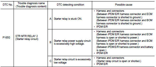
Nissan Juke Service and Repair Manual : P1650 starter motor relay 2
Description
ECM controls ON/OFF state of the starter relay, according to the engine and vehicle condition. Models with no Intelligent Key System transmit a control signal directly to IPDM E/R. On the other hand, models with the Intelligent Key System transmit a control signal to IPDM E/R by way of BCM via CAN communication.
Under normal conditions, ECM controls and maintains the starter relay in OFF state during engine running or “D” position.
When detecting a decrease in engine speed due to rapid deceleration or heavy load condition, ECM controls and reactivates the starter relay.
IPDM E/R detects a control state of starter relay and starter control relay and transmits a feedback signal to ECM via CAN communication.
DTC Logic
DTC DETECTION LOGIC
NOTE
:
• If DTC P1650 is displayed with DTC U1001, perform the trouble diagnosis for
DTC U1001. Refer to EC-569,
"DTC Logic".
• If DTC P1650 is displayed with DTC P0607, perform the trouble diagnosis for DTC P0607. Refer to EC-685, "DTC Logic".
• If DTC P1650 is displayed with B209F or B20A0 of IPDM E/R, perform the trouble diagnosis for B209F or B20A0. Refer to SEC-134, "DTC Logic" or SEC-136, "DTC Logic".
• If DTC P1650 is displayed with B26F9 or B26FA of BCM, perform the trouble diagnosis for B209F or B20A0.
Refer to SEC-128, "DTC Logic" or SEC-130, "DTC Logic".
DTC CONFIRMATION PROCEDURE
1.PRECONDITIONING
If DTC Confirmation Procedure has been previously conducted, always perform the following procedure before conducting the next test.
1. Turn ignition switch OFF and wait at least 10 seconds.
2. Turn ignition switch ON.
3. Turn ignition switch OFF and wait at least 10 seconds.
>> GO TO 2.
2.PERFORM DTC CONFIRMATION PROCEDURE FOR MALFUNCTION A AND C
1. Turn ignition switch OFF and wait at least 10 seconds.
2. Turn ignition switch ON 3. Turn ignition switch OFF and wait at least 10 seconds.
4. Check 1st trip DTC.
Is 1st trip DTC detected? YES >> Proceed to EC-726, "Diagnosis Procedure".
NO >> GO TO 3.
3.PERFORM DTC CONFIRMATION PROCEDURE FOR MALFUNCTION B
 With CONSULT-III
CAUTION:
Always drive at a safe spe
ed.
1. Start the engine.
2. Turn ignition switch OFF and wait at least 10 seconds.
3. Turn ignition switch ON.
4. Start the engine and warm it up to normal operating temperature.
5. Turn ignition switch OFF.
6. Lift up drive wheels.
7. Turn ignition switch ON.
8. Select “POWER BALANCE” in “ACTIVE TEST” mode of “ENGINE” using CONSULT-III.
9. Restart the engine and let it idle at least 10 seconds.
10. Shift the selector lever to D position while depressing fully the brake pedal.
11. Select 1 - 4 cylinders in “POWER BALANCE” and cut the fuel of all cylinders.
12. Check 1st trip DTC.
 Without CONSULT-III
CAUTION:
Always drive at a safe speed.
1. Start the engine.
2. Turn ignition switch OFF and wait at least 10 seconds.
3. Turn ignition switch ON.
4. Start the engine and warm it up to normal operating temperature.
5. Turn ignition switch OFF.
6. Lift up drive wheels.
7. Restart the engine and let it idle at least 10 seconds.
8. Shift the selector lever to D position while depressing fully the brake pedal.
9. Remove vacuum hoses from intake manifold.
10. Check 1st trip DTC.
Is 1st trip DTC detected? YES >> Proceed to EC-726, "Diagnosis Procedure".
NO >> INSPECTION END
Diagnosis Procedure
1.CHECK STARTER RELAY POWER SUPPLY CIRCUIT
Check the starter motor relay power supply circuit. Refer to PCS-33, "Diagnosis Procedure" (With Intelligent Key system) or PCS-62, "Diagnosis Procedure" (Without Intelligent Key system).
Is the inspection result normal? YES >> GO TO 2.
NO >> Repair or replace error-detected parts.
2.CHECK STARTER RELAY CONTROL SIGNAL CIRCUIT
With Intelligent Key system 1. Turn ignition switch OFF.
2. Disconnect IPDM E/R harness connector.
3. Disconnect BCM harness connector.
4. Check the continuity between IPDM E/R harness connector and BCM harness connector.
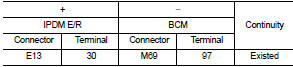
5. Also check harness for short to ground to power.
Without Intelligent Key system 1. Turn ignition switch OFF.
2. Disconnect IPDM E/R harness connector.
3. Disconnect ECM harness connector.
4. Check the continuity between IPDM E/R harness connector and ECM harness connector.
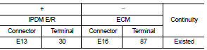
5. Also check harness for short to ground to power.
Is the inspection result normal? YES >> GO TO 3.
NO >> Repair or replace error-detected parts.
3.CHECK INTERMITTENT INCIDENT
Perform GI-42, "Intermittent Incident".
Is the inspection result normal? YES >> Replace IPDM E/R. Refer to PCS-34, "Removal and Installation".
NO >> Repair or replace error-detected parts.
 P1574 ASCD vehicle speed sensor
Description
The ECM receives two vehicle speed sensor signals via CAN communication line.
One is sent from combination
meter, and the other is from TCM (Transmission control module). The ECM uses ...
 P1651 starter motor relay
Description
ECM controls ON/OFF state of the starter relay, according to the engine and
vehicle condition. Models with no
Intelligent Key System transmit a control signal directly to IPDM E/R. On ...
Other materials:
Warning/Indicator lights (yellow)
or
Anti-lock Braking System (ABS) warning light
When you place the power switch in the ON or "READY to drive" position, the Anti-lock Braking System (ABS) warning light will illuminate briefly and then extinguish. This serves as a standard system self-check to confirm ...
Erratic acceleration
Description
CHART 10: Erratic acceleration
Diagnosis Procedure
1.CHECK ECM POWER SUPPLY AND GROUND CIRCUIT
Check ECM power supply and ground circuit. Refer to EC-885, "Diagnosis
Procedure".
Is the inspection result normal?
YES >> GO TO 2.
NO >> Repair or replace ha ...
Turbocharger
Exploded View
1. Exhaust manifold
2. Turbocharger
3. Gasket
4. Turbocharger outlet duct
5. Oil outlet hose
6. Clamp
7. Oil return pipe
8. Gasket
9. Washer
10. Oil supply tube
11. O-ring
A. To EGR tube
B. To air inlet pipe
C. To turbocharge air inlet pipe
D. To diesel partic ...
