Nissan Juke Service and Repair Manual : P1632 fuel cut off valve
DTC Logic
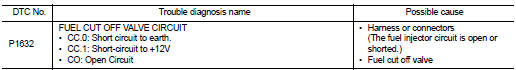
DTC DETECTION LOGIC
Diagnosis Procedure
1.CHECK FUEL CUT OFF VALVE POWER SUPPLY CIRCUIT FOR OPEN AND SHORT
1. Turn ignition switch OFF.
2. Disconnect fuel cut off valve harness connector.
3. Turn ignition switch ON.
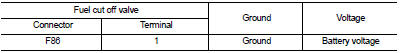
4. Check the voltage between fuel cut off valve harness connector and ground.
Is the inspection result normal? YES >> GO TO 3.
NO >> GO TO 2.
2.DETECT MALFUNCTIONING PART
Check the following.
• Harness connectors E8, F1 • Harness for open or short between IPDM E/R and fuel cut off valve
>> Repair open circuit or short to ground or short to power in harness or connectors.
3.CHECK FUEL CUT OFF VALVE OUTPUT SIGNAL CIRCUIT FOR OPEN AND SHORT
1. Turn ignition switch OFF.
2. Disconnect ECM harness connector.
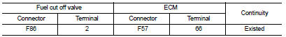
3. Check the continuity between fuel cut off valve harness connector and ECM harness connector.
4. Also check harness for short to ground and short to power.
Is the inspection result normal? YES >> GO TO 4.
NO >> Repair open circuit or short to ground or short to power in harness or connectors.
4.CHECK FUEL CUT OFF VALVE
Refer to EC-989, "Component Inspection".
Is the inspection result normal? YES >> GO TO 5.
NO >> Replace exhaust fuel injector.
5.CHECK INTERMITTENT INCIDENT
Refer to GI-42, "Intermittent Incident".
>> INSPECTION END
Component Inspection
1.CHECK FUEL CUT OFF VALVE
1. Turn ignition switch OFF.
2. Disconnect fuel cut off valve harness connector.
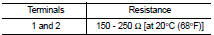
3. Check resistance between fuel cut off valve terminals as follows.
Is the inspection result normal? YES >> INSPECTION END
NO >> Replace fuel cut off valve.
 P160C ECM
DTC Logic
DTC DETECTION LOGIC
Diagnosis Procedure
1.INSPECTION START
1. Turn ignition switch ON.
2. Erase DTC.
3. Turn ignition switch OFF and wait for 20 seconds.
4. Turn ignition switch ON ...
 P1641 thermoplunger control unit
DTC Logic
DTC DETECTION LOGIC
Diagnosis Procedure
1.CHECK THERMOPLUNGER CONTROL UNIT POWER SUPPLY CIRCUIT
1. Turn ignition switch OFF.
2. Disconnect thermoplunger control unit harness connector ...
Other materials:
Corrosion protection
Most common factors contributing to vehicle corrosion
The persistent accumulation of moisture-retaining dirt, road grime, and organic debris within hidden body panel sections, structural cavities, and hard-to-reach areas of your Nissan Leaf.
Compromised integrity of the facto ...
Steering does not lock
Description
Steering does not lock when door is open while ignition switch is OFF.
NOTE:
Before performing the diagnosis, check “Work Flow”. Refer to SEC-47, "Work
Flow".
Diagnosis Procedure
1.CHECK DOOR SWITCH
Check door switch.
Refer to DLK-87, "Component Function C ...
B2620 Park/neutral position switch
DTC Logic
DTC DETECTION LOGIC
DTC CONFIRMATION PROCEDURE
1.PERFORM DTC CONFIRMATION PROCEDURE
1. Turn ignition switch ON and wait 2 seconds or more under the following
conditions.
2. Set shift lever in the Neutral position and wait for 2 seconds or more.
3. Set shift lever in the Reverse p ...
