Nissan Juke Service and Repair Manual : P1544 EGT sensor 2
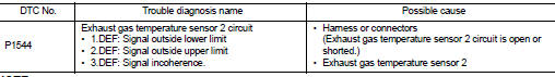
DTC Logic
DTC DETECTION LOGIC
NOTE
:
If DTC P1544 is displayed with DTC P0115, first perform trouble diagnosis for
DTC P0115. Refer to EC-907,
"DTC Logic".
Diagnosis Procedure
1.CHECK GROUND CONNECTIONS
1. Turn ignition switch OFF.
2. Check ground connection E38. Refer to Ground inspection in GI-44, "Circuit Inspection".
Is the inspection result normal? YES >> GO TO 2.
NO >> Repair or replace ground connection.
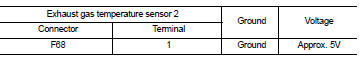
2.CHECK EXHAUST GAS TEMPERATURE SENSOR 2 POWER SUPPLY CIRCUIT
1. Disconnect exhaust gas temperature sensor 2 harness connector.
2. Turn ignition switch ON.
3. Check the voltage between exhaust gas temperature sensor 2 harness connector and ground.
Is the inspection result normal? YES >> GO TO 3.
NO >> Repair open circuit or short to ground or short to power in harness or connectors.
3.CHECK EXHAUST GAS TEMPERATURE SENSOR 2 GROUND CIRCUIT FOR OPEN AND SHORT
1. Turn ignition switch OFF.
2. Disconnect ECM harness connector.
3. Check the continuity between exhaust gas temperature sensor 2 harness connector and ECM harness connector.

4. Also check harness for short to ground and short to power.
Is the inspection result normal? YES >> GO TO 4.
NO >> Repair open circuit or short to ground or short to power in harness or connectors.
4.CHECK INTERMITTENT INCIDENT
Refer to GI-42, "Intermittent Incident".
Is the inspection result normal? YES >> Replace exhaust gas temperature sensor 2.
NO >> Repair or replace.
 P1525 communication circuit for ASCD and speed limiter
DTC Logic
DTC DETECTION LOGIC
...
 P1545 EGT sensor 2
DTC Logic
DTC DETECTION LOGIC
NOTE:
If DTC P1545 is displayed with DTC P1544, first perform trouble diagnosis for
DTC P1544. Refer to EC-985,
"DTC Logic". ...
Other materials:
Precaution Necessary for Steering Wheel Rotation after Battery Disconnect
NOTE:
• Before removing and installing any control units, first turn the ignition
switch to the LOCK position, then disconnect
both battery cables.
• After finishing work, confirm that all control unit connectors are connected
properly, then re-connect both
battery cables.
• Always us ...
Diagnosis system (ECM)
Diagnosis description
Diagnosis description : 1st Trip Detection
Logic and Two Trip Detection Logic
When a malfunction is detected for the first time, 1st trip DTC and 1st trip
Freeze Frame data are stored in the
ECM memory. The MIL will not illuminate at this stage. <1st trip>
If the s ...
Super lock does not operatE
All door
ALL DOOR : Diagnosis Procedure
1.CHECK SUPER LOCK ACTUATOR
Check front driver side super lock actuator.
Refer to DLK-407, "DRIVER SIDE : Component Function Check".
Is the inspection result normal?
YES >> GO TO 2.
NO >> Repair or replace the malfunctioning ...
