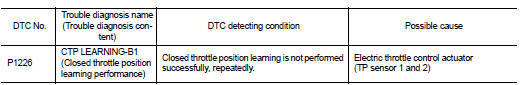
Nissan Juke Service and Repair Manual : P1226 TP sensor
DTC Logic
DTC DETECTION LOGIC
DTC CONFIRMATION PROCEDURE
1.PRECONDITIONING
If DTC Confirmation Procedure has been previously conducted, always perform the following procedure before conducting the next test.
1. Turn ignition switch OFF and wait at least 10 seconds.
2. Turn ignition switch ON.
3. Turn ignition switch OFF and wait at least 10 seconds.
TESTING CONDITION:
Before performing the following procedure, confirm that battery voltage is more
than 10 V at idle.
>> GO TO 2.
2.PERFORM DTC CONFIRMATION PROCEDURE
1. Turn ignition switch ON.
2. Turn ignition switch OFF, wait at least 10 seconds.
3. Turn ignition switch ON.
4. Repeat steps 2 and 3 for 32 times.
5. Check 1st trip DTC.
Is 1st trip DTC detected? YES >> Proceed to EC-327, "Diagnosis Procedure".
NO >> INSPECTION END
Diagnosis Procedure
1.CHECK ELECTRIC THROTTLE CONTROL ACTUATOR VISUALLY
1. Turn ignition switch OFF.
2. Remove the intake air duct. Refer to EM-26, "Exploded View".
3. Check if foreign matter is caught between the throttle valve and the housing.
Is the inspection result normal? YES >> Replace electric throttle control actuator. Refer to EM-28, "Exploded View".
NO >> Remove the foreign matter and clean the electric throttle control actuator inside, then perform throttle valve closed position learning. Refer to EC-135, "Work Procedure".
 P1225 TP sensor
DTC Logic
DTC DETECTION LOGIC
DTC CONFIRMATION PROCEDURE
1.PRECONDITIONING
If DTC Confirmation Procedure has been previously conducted, always perform
the following procedure
before conductin ...
 P1550 battery current sensor
DTC Logic
DTC DETECTION LOGIC
DTC CONFIRMATION PROCEDURE
1.PRECONDITIONING
If DTC Confirmation Procedure has been previously conducted, always perform
the following before conducting
the next ...
Other materials:
Body alignment
Body Center Marks (RHD Models)
A mark is placed on each part of the body to indicate the vehicle center.
When repairing the vehicle frame
(members, pillars, etc.) damaged by an accident which it enables more accurate
and effective repair by using
these marks together with body alignment speci ...
How to normal charge (AC 220-240 volt) by charging device
WARNING
If you utilize any medical electronic devices, such as an implantable cardiac pacemaker or an implantable cardiovascular defibrillator, please consult with the manufacturer of that device regarding the potential effects that the electromagnetic environment during charging may ...
B2267 engine speed
Description
The engine speed signal is transmitted from ECM to the combination meter via
CAN communication.
DTC Logic
DTC DETECTION LOGIC
Diagnosis Procedure
1.PERFORM SELF-DIAGNOSIS OF ECM
Perform “Self Diagnostic Result” of “ENGINE”, and repair or replace
malfunctioning parts.
...
