Nissan Juke Service and Repair Manual : P0409 EGR volume control valve control position sensor
DTC Logic
DTC DETECTION LOGIC
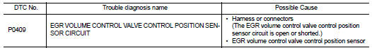
Diagnosis Procedure
1.CHECK GROUND CONNECTIONS
1. Turn ignition switch OFF.
2. Check ground connection E38. Refer to Ground inspection in GI-44, "Circuit Inspection".
Is the inspection result normal? YES >> GO TO 2.
NO >> Repair or replace ground connection.
2.CHECK EGR VOLUME CONTROL VALVE CONTROL POSITION SENSOR POWER SUPPLY CIRCUIT
1. Disconnect EGR volume control valve harness connector.
2. Turn ignition switch ON.
3. Check the voltage between EGR volume control valve control position sensor connector and ground.
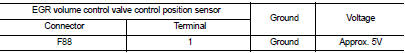
Is the inspection result normal? YES >> GO TO 3.
NO >> Repair open circuit or short to ground or short to power in harness or connectors.
3.CHECK EGR VOLUME CONTROL VALVE CONTROL POSITION SENSOR GROUND CIRCUIT FOR OPEN AND SHORT
1. Turn ignition switch OFF.
2. Disconnect ECM harness connector.
3. Check the continuity between EGR volume control valve control position sensor harness connector and ECM harness connector.
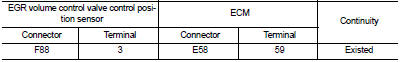
4. Also check harness for short to ground and short to power.
Is the inspection result normal? YES >> GO TO 4.
NO >> Repair open circuit or short to ground or short to power in harness or connectors.
4.CHECK EGR VOLUME CONTROL VALVE CONTROL POSITION SENSOR INPUT CIRCUIT FOR OPEN AND SHORT
1. Check the continuity between EGR volume control valve control position sensor harness connector and ECM harness connector.
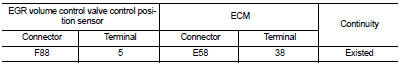
2. Also check harness for short to ground and short to power.
Is the inspection result normal? YES >> GO TO 5.
NO >> Repair open circuit or short to ground or short to power in harness or connectors.
5.CHECK INTERMITTENT INCIDENT
Refer to GI-42, "Intermittent Incident", ???INCIDENT SIMULATION TESTS??? and ???GROUND INSPECTION???.
Is the inspection result normal? YES >> GO TO 6.
NO >> Repair or replace.
6.REPLACE EGR VOLUME CONTROL VALVE
1. Replace the EGR volume control valve.
2. Perform EC-881, "Work Procedure"
>> INSPECTIO END
 P0403 EGR volume control valve
DTC Logic
DTC DETECTION LOGIC
Diagnosis Procedure
1.CHECK EGR VOLUME CONTROL VALVE CONTROL CIRCUIT
1. Turn ignition switch OFF.
2. Disconnect EGR volume control valve harness connector and ECM ...
 P0470 exhaust gas pressure sensor 1
DTC Logic
DTC DETECTION LOGIC
NOTE:
If DTC P0470 is displayed with DTC P0651 or P2263, first perform trouble
diagnosis for DTC P0651 or P2263.
Refer to EC-975, "DTC Logic" (P0651), ...
Other materials:
Insufficient cooling
Description
Symptom
• Insufficient cooling
• No cool air comes out. (Air flow volume is normal.)
Diagnosis Procedure
NOTE:
Perform self-diagnoses with CONSULT-III before performing symptom diagnosis. If
any DTC is detected, perform
the corresponding diagnosis.
1.CHECK MAGNET CLUTCH O ...
Fuel tank
2WD : Exploded View
1. Fuel filler cap
2. Grommet
3. Fuel filler tube
4. EVAP canister hose
5. Fuel tank mounting band (RH)
6. Fuel tank mounting band (LH)
7. Fuel tank
8. Clamp
9. Fuel filler hose
10. Vent hose
Vehicle front
: N?·m (kg-m, ft-lb)
2WD : Removal and Installation ...
Diagnosis and repair workflow
Work Flow
OVERALL SEQUENCE
DETAILED FLOW
1.INTERVIEW FOR MALFUNCTION
Interview the symptom to the customer
>> GO TO 2.
2.SYMPTOM CHECK
Check the symptom from the customer's information. Check that any symptom
occurs other than the interviewed
symptom.
Insufficient cooling/heat ...
