Nissan Juke Service and Repair Manual : P0403 EGR volume control valve
DTC Logic
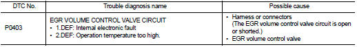
DTC DETECTION LOGIC
Diagnosis Procedure
1.CHECK EGR VOLUME CONTROL VALVE CONTROL CIRCUIT
1. Turn ignition switch OFF.
2. Disconnect EGR volume control valve harness connector and ECM harness connector.
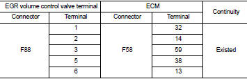
3. Check the continuity between EGR volume control valve terminal harness connector and ECM harness connector
4. Also check harness for short to ground and short to power.
OK or NG OK >> GO TO 2.
NG >> Repair open circuit or short to ground or short to power in harness or connectors.
2.CHECK EGR VOLUME CONTROL VALVE
Refer to EC-941, "Component Inspection".
OK or NG OK >> GO TO 3.
NG >> Replace EGR volume control valve.
3.CHECK EGR VOLUME CONTROL VALVE CONTROL POSITION SENSOR
Refer to EC-941, "Component Inspection".
OK or NG OK >> GO TO 4.
NG >> Replace EGR volume control valve.
4.CHECK EGR PASSAGE
Check the following for clogging and cracks.
ŌĆó EGR tube
ŌĆó EGR hose
ŌĆó EGR cooler
OK or NG OK >> GO TO 5.
NG >> Repair or replace EGR passage.
5.CHECK INTERMITTENT INCIDENT
Refer to GI-42, "Intermittent Incident".
>> INSPECTION END
Component Inspection
EGR VOLUME CONTROL VALVE
1. Disconnect EGR volume control valve harness connector.
2. Check resistance EGR volume control valve harness connector.
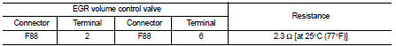
If NG, replace EGR volume control valve. Refer to EC-881, "Work Procedure".
EGR VOLUME CONTROL VALVE CONTROL POSITION SENSOR
1. Disconnect EGR volume control valve harness connector.
2. Check continuity EGR volume control valve harness connector.
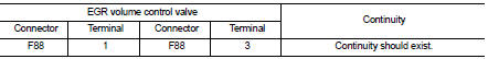
If NG, replace EGR volume control valve. Refer to EC-881, "Work Procedure".
 P0402 EGR volume control valve
DTC Logic
DTC DETECTION LOGIC
Diagnosis Procedure
1.CHECK GROUND CONNECTIONS
1. Turn ignition switch OFF.
2. Check ground connection E38. Refer to Ground inspection in GI-44, "Circuit
In ...
 P0409 EGR volume control valve control position sensor
DTC Logic
DTC DETECTION LOGIC
Diagnosis Procedure
1.CHECK GROUND CONNECTIONS
1. Turn ignition switch OFF.
2. Check ground connection E38. Refer to Ground inspection in GI-44, "Circuit
In ...
Other materials:
B2013 steering lock unit
DTC Logic
DTC DETECTION LOGIC
DTC CONFIRMATION PROCEDURE
1.PERFORM DTC CONFIRMATION PROCEDURE
1. Lock the steering.
NOTE:
3. Press the push-button ignition switch.
4. Check DTC in ŌĆ£Self Diagnostic ResultŌĆØ mode of ŌĆ£BCMŌĆØ using CONSULT-III.
Is DTC detected?
YES >> Go to S ...
How to normal charge (AC 220-240 volt) by charging device
WARNING
If you utilize any medical electronic devices, such as an implantable cardiac pacemaker or an implantable cardiovascular defibrillator, please consult with the manufacturer of that device regarding the potential effects that the electromagnetic environment during charging may ...
Insufficient heating
Description
Symptom
ŌĆó Insufficient heating
ŌĆó No warm air comes out. (Air flow volume is normal.)
Diagnosis Procedure
NOTE:
Perform self-diagnosis with CONSULT-III before performing symptom diagnosis. If
any malfunction result or
DTC is detected, perform the corresponding diagnosis.
1 ...
