Nissan Juke Service and Repair Manual : P0222, P0223 TP sensor
DTC Logic
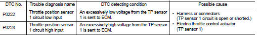
DTC DETECTION LOGIC
NOTE
:
If DTC P0222 or P0223 is displayed with DTC P0643, first perform the trouble
diagnosis for DTC P0643.
Refer to EC-686, "DTC Logic".
DTC CONFIRMATION PROCEDURE
1.PRECONDITIONING
If DTC Confirmation Procedure has been previously conducted, always turn ignition switch OFF and wait at least 10 seconds before conducting the next test.
TESTING CONDITION:
Before performing the following procedure, confirm that battery voltage is more
than 10 V at idle.
>> GO TO 2.
2.PERFORM DTC CONFIRMATION PROCEDURE
1. Start engine and let it idle for 1 second.
2. Check DTC.
Is DTC detected? YES >> Go to EC-645, "Diagnosis Procedure".
NO >> INSPECTION END
Diagnosis Procedure
1.CHECK GROUND CONNECTION
1. Turn ignition switch OFF.
2. Check ground connection E21 and E38. Refer to Ground Inspection in GI-44, "Circuit Inspection".
Is the inspection result normal? YES >> GO TO 2.
NO >> Repair or replace ground connection.
2.CHECK THROTTLE POSITION SENSOR 1 POWER SUPPLY CIRCUIT
1. Disconnect electric throttle control actuator harness connector.
2. Turn ignition switch ON.
3. Check the voltage between electric throttle control actuator harness connector and ground.
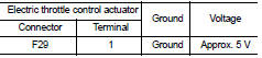
Is the inspection result normal? YES >> GO TO 3.
NO >> Repair open circuit or short to ground or short to power in harness or connectors.
3.CHECK THROTTLE POSITION SENSOR 1 GROUND CIRCUIT FOR OPEN AND SHORT
1. Turn ignition switch OFF.
2. Disconnect ECM harness connector.
3. Check the continuity between electric throttle control actuator harness connector and ECM harness connector.
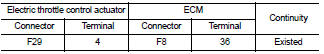
4. Also check harness for short to ground and short to power.
Is the inspection result normal? YES >> GO TO 4.
NO >> Repair open circuit or short to ground or short to power in harness or connectors.
4.CHECK THROTTLE POSITION SENSOR 1 INPUT SIGNAL CIRCUIT FOR OPEN AND SHORT
1. Check the continuity between electric throttle control actuator harness connector and ECM harness connector.
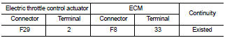
2. Also check harness for short to ground and short to power.
Is the inspection result normal? YES >> GO TO 5.
NO >> Repair open circuit or short to ground or short to power in harness or connectors.
5.CHECK THROTTLE POSITION SENSOR
Refer to EC-646, "Component Inspection".
Is the inspection result normal? YES >> GO TO 7.
NO >> GO TO 6.
6.REPLACE ELECTRIC THROTTLE CONTROL ACTUATOR
Replace electric throttle control actuator. Refer to EM-163, "Exploded View".
>> INSPECTION END
7.CHECK INTERMITTENT INCIDENT
Refer to GI-42, "Intermittent Incident".
>> INSPECTION END
Component Inspection
1.CHECK THROTTLE POSITION SENSOR
1. Turn ignition switch OFF.
2. Reconnect all harness connectors disconnected.
3. Perform EC-543, "Work Procedure".
4. Turn ignition switch ON.
5. Set selector lever to D (CVT) or 1st (M/T) position.
6. Check the voltage between ECM harness connector and ground.
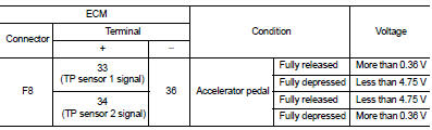
Is the inspection result normal? YES >> INSPECTION END
NO >> GO TO 2.
2.REPLACE ELECTRIC THROTTLE CONTROL ACTUATOR
Replace electric throttle control actuator. Refer to EM-163, "Exploded View".
>> INSPECTION END
 P0197, P0198 EOT sensor
DTC Logic
DTC DETECTION LOGIC
DTC CONFIRMATION PROCEDURE
1.PRECONDITIONING
If DTC Confirmation Procedure has been previously conducted, always perform
the following procedure
before conductin ...
 P0300, P0301, P0302, P0303, P0304 misfire
DTC Logic
DTC DETECTION LOGIC
When a misfire occurs, engine speed will fluctuate. If the engine speed
fluctuates enough to cause the crankshaft
position (CKP) sensor (POS) signal to vary, ECM can ...
Other materials:
Rear wiper motor circuit
Component Function Check
1.CHECK REAR WIPER ON OPERATION
CONSULT-III ACTIVE TEST
1. Select “RR WIPER” of BCM active test item.
2. With operating the test item, check rear wiper operation.
On : Rear wiper ON operation
Off : Stop the rear wiper.
Is rear wiper operation normally?
YES >&g ...
C1109 power and ground system
DTC Logic
DTC DETECTION LOGIC
DTC CONFIRMATION PROCEDURE
1.PRECONDITIONING
If “DTC CONFIRMATION PROCEDURE” has been previously conducted, always turn
ignition switch OFF and
wait at least 10 seconds before conducting the next test.
>> GO TO 2.
2.CHECK DTC DETECTION
With CON ...
B1134 side air bag module LH
DTC Logic
DTC DETECTION LOGIC
DTC CONFIRMATION PROCEDURE
1.CHECK SELF-DIAG RESULT
With CONSULT-III
1. Turn ignition switch ON.
2. Perform “Self Diagnostic Result” mode of “AIR BAG” using CONSULT-III.
Without CONSULT-III
1. Turn ignition switch ON.
2. Check the air bag warning la ...
