Nissan Juke Service and Repair Manual : Component parts
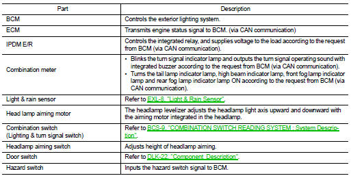
Component Parts Location
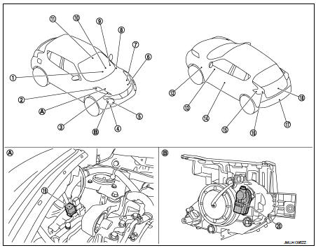
1. Hazard switch
2. Parking lamp
3. Front turn signal lamp
4. Front fog lamp*1
5. Headlamp
6. ECM
Refer to EC-461, "ECM".
7. IPDM E/R Refer to PCS-5, "Component Parts Location".
8. BCM Refer to BCS-6, "BODY CONTROL SYSTEM : Component Parts Location".
9. Combination switch
10. Combination meter
11. Light & rain sensor*2
12. Side turn signal lamp
13. Headlamp aiming switch
14. Front door switch (driver side)
15. Rear turn signal lamp
16. Tail lamp
17. Rear fog lamp
18. License plate lamp
19. Daytime running light relay*3
20. Aiming motor
A. Engine room (RH)
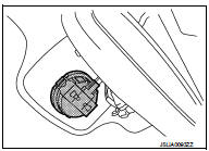
B. Headlamp (back)
*1: With front fog lamp models *2: With auto light system *3: With daytime running light system
Component Description
Light & Rain Sensor
• The light & rain sensor detects the outside ambient light level, forward light level and sensor conditions.
• Based on ambient light level (day/night detection), forward light level (tunnel detection) and sensor conditions it judges ON/OFF condition for exterior lamps.
• And it transmits exterior lamp ON/OFF request to the BCM by the light & rain sensor serial link.
• BCM controls each function depending on the signals. And it detects the light & rain sensor serial link error and the light & rain sensor malfunction.

 System
Headlamp system
HEADLAMP SYSTEM : System Diagram
HEADLAMP SYSTEM : System Description
OUTLINE
Headlamp is controlled by combination switch reading function and headlamp
control function of BCM ...
Other materials:
Cockpit
1. Outside mirror remote control switch
2. Headlight, fog light and turn signal switch
— Headlight
— Turn signal light
— Fog light
3. Steering wheel
— Electric power steering system
— Horn
— Driver’s supplemental air bag
4. Wiper and washer switch
5. Shift lever
— Contin ...
C1105, C1106, C1107, C1108 wheel sensor
DTC Logic
DTC DETECTION LOGIC
DTC CONFIRMATION PROCEDURE
1.PRECONDITIONING
If “DTC CONFIRMATION PROCEDURE” has been previously conducted, always turn
ignition switch OFF and
wait at least 10 seconds before conducting the next test.
>> GO TO 2.
2.CHECK DTC DETECTION
With CONSU ...
Diagnosis system (BCM)
Common item
COMMON ITEM : CONSULT-III Function (BCM - COMMON ITEM)
APPLICATION ITEM
CONSULT-III performs the following functions via CAN communication with BCM.
SYSTEM APPLICATION
BCM can perform the following functions for each system.
NOTE:
It can perform the diagnosis modes except the ...
