Nissan Juke Service and Repair Manual : P0190 FRP sensor
DTC Logic
DTC DETECTION LOGIC
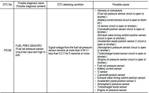
DTC CONFIRMATION PROCEDURE
1.PRECONDITIONING
If DTC Confirmation Procedure has been previously conducted, always perform the following procedure before conducting the next test.
1. Turn ignition switch OFF and wait at least 10 seconds.
2. Turn ignition switch ON.
3. Turn ignition switch OFF and wait at least 10 seconds.
TESTING CONDITION:
Before performing the following procedure, confirm that battery voltage is 11 V
or more at idle.
>> GO TO 2.
2.PERFORM DTC CONFIRMATION PROCEDURE
1. Start the engine ON and wait at least 60 seconds.
2. Check DTC or 1st trip DTC.
Is DTC or 1st trip DTC detected? YES >> Proceed to EC-247, "Diagnosis Procedure".
NO >> INSPECTION END
Diagnosis Procedure
1.CHECK FUEL RAIL PRESSURE (FRP) SENSOR POWER SUPPLY-I
1. Turn ignition switch OFF.
2. Disconnect FRP sensor connector.
3. Turn ignition switch ON.
4. Check the voltage between FRP sensor harness connector terminals.
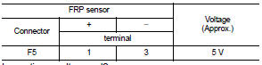
Inspection result normal? YES >> GO TO 6.
NO >> GO TO 2.
2.CHECK FRP SENSOR POWER SUPPLY-II
Check the voltage between FRP sensor harness connector and the ground.
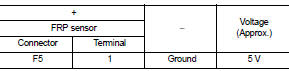
Is inspection result normal? YES >> GO TO 4.
NO >> GO TO 3.
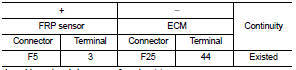
3.CHECK SENSOR POWER SUPPLY CIRCUIT
1. Turn ignition switch OFF.
2. Disconnect ECM harness connector.
3. Check harness connector for short to power and short to ground, between the following terminals.
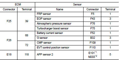
*1: LHD models or RHD with CVT models *2: RHD with M/T models
Is inspection result normal? YES >> Perform the trouble diagnosis for power supply circuit.
NO >> Repair or replace error-detected parts.
4.CHECK FRP SENSOR GROUND CIRCUIT
1. Turn ignition switch OFF.
2. Disconnect ECM harness connector.
3. Check the continuity between FRP sensor harness connector and ECM harness connector.
4. Also check harness for short to power.
Is inspection result normal? YES >> GO TO 5.
NO >> Repair or replace error-detected parts.
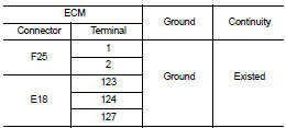
5.CHECK ECM GROUND CIRCUIT
Check the continuity between ECM harness connector and the ground.
Is inspection result normal? YES >> Check intermittent incident. Refer to GI-42, "Intermittent Incident".
NO >> Repair or replace error-detected parts.
6.CHECK FRP SENSOR SIGNAL CIRCUIT
1. Turn ignition switch OFF.
2. Disconnect ECM harness connector.
3. Check the continuity between FRP sensor harness connector and ECM harness connector.
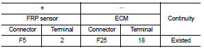
4. Also check harness for short to ground and to power.
Is inspection result normal? YES >> GO TO 7.
NO >> Repair or replace error-detected parts.
7.CHECK FRP SENSOR
Check the FRP sensor. Refer to EC-249, "Component Inspection".
Is inspection result normal? YES >> Check intermittent incident. Refer to GI-42, "Intermittent Incident".
NO >> Repair or replace error-detected parts.
Component Inspection
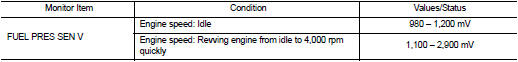
1.CHECK FRP SENSOR
 WITH CONSULT-III
1. Turn ignition switch OFF.
2. Reconnect harness connector disconnected.
3. Start the engine.
4. Select “DATA MONITOR” mode of “ENGINE” using CONSULT-III.
5. Check that the “FUEL PRES SEN V” indication.
 WITHOUT CONSULT-III
1. Turn ignition switch OFF.
2. Reconnect harness connector disconnected.
3. Start the engine.
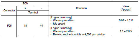
4. Check FRP sensor signal voltage.
Is the inspection result normal? YES >> INSPECTION END.
NO >> Replace FRP sensor. Refer to EM-47, "Exploded View".
 P0172 fuel injection system function
DTC Logic
DTC DETECTION LOGIC
With the Air/Fuel Mixture Ratio Self-Learning Control, the actual mixture
ratio can be brought closely to the
theoretical mixture ratio based on the mixture ratio fe ...
 P0197, P0198 EOT sensor
DTC Logic
DTC DETECTION LOGIC
DTC CONFIRMATION PROCEDURE
1.PRECONDITIONING
If DTC Confirmation Procedure has been previously conducted, always perform
the following procedure
before conductin ...
Other materials:
P0730 incorrect gear ratio
DTC Logic
DTC DETECTION LOGIC
DTC CONFIRMATION PROCEDURE
NOTE:
If “DTC CONFIRMATION PROCEDURE” has been previously performed, always turn
ignition switch
OFF and wait at least 10 seconds before performing the next test.
After the repair, perform the following procedure to confirm the ...
Checking bulbs
With all doors closed, apply the parking brake and place the ignition switch
in the ON position without starting the engine. The following lights will come on:
,
or
,
,
,
,
,
The following lights come on briefly and then go off (if so equipped):
,
or
,
,
,
,
,
,
,
,
,
If ...
Fuel filler lid opener
Exploded View
1. Fuel filler lid opener cable
2. Cable protector
3. Fuel filler lid lock assembly
4. Fuel filler lid assembly
5. Spring
6. Bumper rubber
: Clip
: Do not reuse
Fuel filler lid
FUEL FILLER LID : Removal and Installation
REMOVAL
1. Fully open fuel filler lid.
2. Remov ...
