
Nissan Leaf 2018-2025 (ZE1) Owner's Manual : Operating range
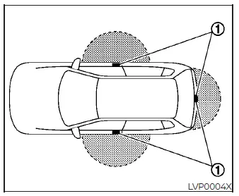
The integrated NISSAN Intelligent Key functions are programmed to respond only when the transmitter fob is positioned within the specifically engineered proximity operating range from each localized door or hatch request switch 1.
When the internal coin-cell battery of the Intelligent Key is nearly depleted, or if heavy electromagnetic interference or strong radio waves are present near your current parking location, the effective operating radius of the system will contract noticeably, which may cause the transmitter to respond intermittently or fail to recognize commands.
Under normal, unobstructed conditions, the maximum responsive operating range is measured within 31.5 inches (80 cm) from each individual exterior handle request switch 1.
If the key fob is held too flush against the side door glass, directly against the structural handle housing, or too close to the rear bumper assembly, the localized sensors may experience dead zones and fail to trigger.
Please be aware that whenever the matching Intelligent Key is resting anywhere within this active external perimeter, the system is fully unlocked to authorized inputs; consequently, anyone standing by the vehicle can press the handle request switch to lock or unlock the passenger doors and rear hatch, even if they are not personally carrying the key fob.
Door locks/unlocks precaution
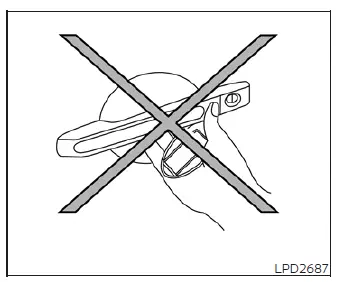
- Avoid pinching or squeezing the exterior door handle request switch while holding the key fob directly in that same hand, as demonstrated in the diagram. This extremely close positioning blocks proper wave propagation, making it highly difficult for the security sensors to confirm whether the transponder is located safely outside or inside the Nissan Leaf cabin.
- Immediately after pressing the request switch to secure your vehicle, manually test the handle assembly to visually verify that all door latches have properly engaged into their fully locked configurations.
- To eliminate the possibility of accidentally leaving your primary transmitter locked inside the cabin, make it a firm habit to physically verify the key fob is in your pocket or bag before using external touch points to lock up.
- Do not apply outward pressure or pull the physical handle lever prior to pressing the rubber request switch. If you pull prematurely, the electronic lock actuator will disengage the lock cylinder but the mechanical latch will jam, preventing the door from swinging open.
If this occurs, simply release the door handle completely to reset the internal alignment, then pull it a second time to open the door smoothly.
 NISSAN Intelligent Key system
WARNING
The radio frequency signals emitted by this keyless access system could potentially interfere with the proper function of active electromedical devices. Individuals equipped wit ...
 NISSAN Intelligent Key Operation
This hands-free proximity system allows you to completely secure or access your vehicle cabin without ever needing to physically retrieve the Intelligent Key transmitter from you ...
Other materials:
12-volt battery saver system
To preserve the operational integrity of your electric vehicle, an automated 12-volt battery saver system is integrated into the vehicle's power management logic. When all the following specific operating conditions are simultaneously met and sustained for a predetermined perio ...
Cold weather driving
CAUTION
To maintain the long-term integrity and health of your Nissan Leaf Li-ion battery, it is crucial that you do not store the vehicle in ambient temperatures below -13ºF (-25ºC) for a duration exceeding seven days. When the external temperature reaches -13ºF (-25ºC) or lower, the batte ...
Control cable
Exploded View
1. Control cable
2. Lock plate
3. Transaxle assembly
4. Bracket A
5. Bracket B
6. CVT shift selector assembly
A: Manual lever B: Grommet
: N·m (kg-m, ft-lb)
: N·m (kg-m, in-lb)
Removal and Installation
INSTALLATION
CAUTION:
Always apply the parking brake before per ...
