
Nissan Juke Owners Manual : NISSAN Vehicle Immobilizer System keys
Your vehicle can only be driven with the master keys which are registered to the NISSAN Vehicle Immobilizer System components in your vehicle. These keys have a transponder chip in the key head.
Never leave these keys in the vehicle.
Additional or replacement keys:
If you still have a key, the key number is not necessary when you need extra NISSAN Vehicle Immobilizer System keys. Your dealer can duplicate your existing key. As many as 5 keys can be used with one vehicle. You should bring all the registered keys that you have to a NISSAN dealer for registration. This is because the registration process will erase the memory of all key codes previously registered into the NISSAN Vehicle Immobilizer System. After the registration process, these components will only recognize keys coded into the NISSAN Vehicle Immobilizer System during registration. Any key that is not given to your dealer at the time of registration will no longer be able to start your vehicle.
CAUTION
Do not allow the NISSAN Vehicle Immobilizer System key, which contains an electrical transponder, to come in contact with salt water. This could cause the system to malfunction.
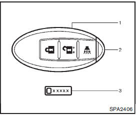
1. Intelligent Key (2 sets) 2. Mechanical key (inside Intelligent Key) (2 sets) 3. Key number plate
 Keys
Keys
A key number plate is supplied with your keys.
Record the key number and keep it in a safe place (such as your wallet), not
in the vehicle. If you lose your keys, see a NISSAN dealer for duplicates ...
 Intelligent Keys (if so equipped)
Your vehicle can only be driven with the Intelligent Keys which are registered
to your vehicle’s Intelligent Key system components and NISSAN Vehicle Immobilizer
System components.
As many as 4 ...
Other materials:
P0712 transmission fluid temperature sensor A
DTC Logic
DTC DETECTION LOGIC
DTC CONFIRMATION PROCEDURE
1.PREPARATION BEFORE WORK
If another "DTC CONFIRMATION PROCEDURE" occurs just before, turn ignition
switch OFF and wait for at
least 10 seconds, then perform the next test.
>> GO TO 2.
2.PERFORM DTC CONFIRMATION ...
Blower motor
Diagnosis Procedure
1.CHECK SYMPTOM
Check symptom (A, B or C).
Which symptom is detected?
A >>GO TO 2.
B >>GO TO 11.
C >> GO TO 13.
2.CHECK FUSE
1. Turn ignition switch OFF.
2. Check following fuses.
- 10A fuse [No. 15, located in fuse block (J/B)]
- 15A fuses [Nos ...
Vehicle speed sensing auto lock operation does not operate
Diagnosis Procedure
1.CHECK “AUTOMATIC LOCK/UNLOCK SELECT� SETTING IN “WORK SUPPORT�
1. Select “DOOR LOCK� of “BCM� using CONSULT-III.
2. Select “AUTOMATIC LOCK/UNLOCK SELECT� in “WORK SUPPORT� mode.
3. Check “AUTOMATIC LOCK/UNLOCK SELECT� setting in “WORK SUPPORT†...
