Nissan Juke Service and Repair Manual : Microphone signal circuit
Description
Power is supplied from audio unit to microphone. The microphone transmits the sound voice to the audio unit.
Diagnosis Procedure
1.CHECK CONTINUITY BETWEEN AUDIO UNIT AND MICROPHONE CIRCUIT
1. Turn ignition switch OFF.
2. Disconnect audio unit connector and microphone connector.
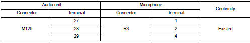
3. Check continuity between audio unit harness connector and microphone harness connector.
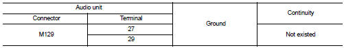
4. Check continuity between audio unit harness connector and ground.
Is inspection result OK? YES >> GO TO 2.
NO >> Repair harness or connector.
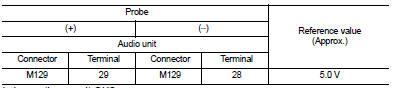
2.CHECK VOLTAGE MICROPHONE VCC
1. Connect audio unit connector.
2. Turn ignition switch ON.
3. Check voltage between audio unit harness connector and ground.
Is inspection result OK? YES >> GO TO 3.
NO >> Replace audio unit. Refer to AV-38, "Removal and Installation".
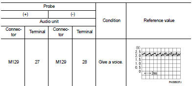
3.CHECK MICROPHONE SIGNAL
1. Turn ignition switch OFF.
2. Connect microphone connector.
3. Turn ignition switch ON.
4. Check signal between audio unit harness connector.
Is inspection result OK? YES >> Replace audio unit. Refer to AV-38, "Removal and Installation".
NO >> Replace microphone. Refer to AV-43, "Removal and Installation".
 Power supply and ground circuit
AUDIO UNIT
AUDIO UNIT : Diagnosis Procedure
1.CHECK FUSE
Check for blown fuses.
Is inspection result OK?
YES >> GO TO 2.
NO >> Be sure to eliminate cause of malfunction before in ...
 Steering switch signal a circuit
Description
Transmits the steering switch signal to audio unit.
Diagnosis Procedure
1.CHECK STEERING SWITCH SIGNAL A CIRCUIT
1. Disconnect audio unit connector and spiral cable connector.
2. Chec ...
Other materials:
Normal operating condition
Description
FUEL CUT CONTROL (AT NO LOAD AND HIGH ENGINE SPEED)
If the engine speed is above 1,800 rpm under no load (for example, the
selector lever position is neutral and
engine speed is over 1,800 rpm) fuel will be cut off after some time. The exact
time when the fuel is cut off varies
b ...
B1209 frontal collision detection
Description
The air bags and seat belt pre-tensioners for driver and passenger are
activated by the air bag diagnosis sensor
unit signal transmitted at the time of the frontal collision.
DTC Logic
DTC DETECTION LOGIC
DTC CONFIRMATION PROCEDURE
1.CHECK SELF-DIAG RESULT
With CONSULT-III
1. ...
B2098 ignition relay on stuck
Description
The ignition relay integrated in IPDM E/R is operated with ignition switch ON
signal from the ignition switch.
DTC Logic
DTC DETECTION LOGIC
1.PERFORM DTC CONFIRMATION PROCEDURE
1. Turn ignition switch ON.
2. Check DTC in ÔÇťSelf Diagnostic ResultÔÇŁ mode of ÔÇťIPDM E/RÔÇŁ usin ...
