Nissan Juke Service and Repair Manual : Lubricant
Description
MAINTENANCE OF LUBRICANT LEVEL
The compressor lubricant is circulating in the system together with the refrigerant. It is necessary to fill compressor with lubricant when replacing A/C system parts or when a large amount of refrigerant leakage is detected. It is important to always maintain lubricant level within the specified level. Otherwise, the following conditions may occur.
• Insufficient lubricant amount: Stuck compressor • Excessive lubricant amount: Insufficient cooling (caused by insufficient heat exchange)
Name : A/C System Oil Type R
Inspection
If a compressor is malfunctioning (internal noise, insufficient cooling), check the compressor oil.
1.COMPRESSOR OIL JUDGMENT
1. Remove the compressor. Refer to HA-32, "COMPRESSOR : Removal and Installation".
2. Sample a compressor oil and judge on the figure.
Judgement result 1>>Replace compressor only.
Judgement result 2>>Replace compressor and liquid tank.
Perform Lubricant Return Operation
CAUTION:
If a large amount of refrigerant or lubricant leakage is detected, never perform
lubricant return operation.
1. Start the engine and set to the following conditions.
• Engine speed: Idling to 1,200 rpm
• A/C switch: ON
• Fan speed: Maximum speed set
• Intake door position: Recirculation
• Temperature setting: Full cold
2. Perform lubricant return operation for approximately 10 minutes.
3. Stop the engine.
4. Lubricant return operation is complete.
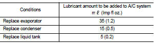
Lubricant Adjusting Procedure for Components Replacement Except Compressor
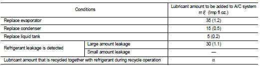
Fill with lubricant for the amount that is calculated according to the following conditions.
Example: Lubricant amount to be added when replacing evaporator and liquid tank [m (Imp fl oz.)] = 35 (1.2) + 5 (0.2) + α
Lubricant Adjusting Procedure for Compressor Replacement
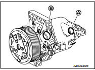
1. Drain lubricant from removed compressor and measure lubricant amount.
1. Drain lubricant from high-pressure port (A) and low-pressure port (B) while rotating magnet clutch.
2. Measure total amount of lubricant that is drained from removed compressor.
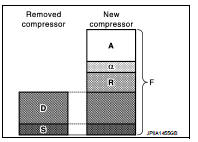
2. Drain lubricant from a new compressor that is calculated according to the following conditions.
Amount to be drained (A) [m (Imp fl oz.)] = F − (D
+ S + R + α)
F : Lubricant amount that a new compressor
contains [120 (4.2)]
D : Lubricant amount that is drained from removed
compressor
S : Lubricant amount that remains inside of removed
compressor [20 (0.7)]
R : Lubricant amount to be added according to
components that are removed except compressor
α : Lubricant amount that is recycled together
with refrigerant during recycle operation
CAUTION: If lubricant amount that is drained from removed compressor is less than 60 m (2.1 Imp fl oz.), perform calculation by setting “D” as 40 m (1.4 Imp fl oz.).
Example: Lubricant amount to be drained from a new compressor when replacing compressor and liquid tank [m (Imp fl oz.)] [D = 60 (2.1), α = 5 (0.2)] 120 (4.2) − [60 (1.6) + 20 (0.7) + 5 (0.2) + 5 (0.2)] = 30 (1.0)
3. Install compressor and check the operation.
 Refrigerant
Description
CONNECTION OF SERVICE TOOLS AND EQUIPMENT
1. Shut-off valve
2. A/C service valve
3. Recovery/recycling/recharging
equipment
4. Vacuum pump
5. Manifold gauge set
6. Refrigerant ...
 Performance test
Inspection
INSPECTION PROCEDURE
1. Connect recovery/recycling/recharging equipment (for HFC-134a) or manifold
gauge.
2. Start the engine, and set to the following condition.
Test condition
...
Other materials:
Parts Requiring Angle Tightening
• Use the angle wrench [SST: KV10112100] for the final tightening of the
following engine parts:
- Camshaft sprocket (INT) bolt
- Cylinder head bolts
- Main bearing cap bolts
- Connecting rod cap bolts
- Crankshaft pulley bolt (No the angle wrench is required as bolt flange is
provided wi ...
The seat belt reminder warning continues sounding, or
does not sound
Description
• Seat belt reminder warning does not sound.
• Seat belt reminder warning sounds continuously.
Diagnosis Procedure
1.CHECK SEAT BELT WARNING LAMP
1. Turn ignition switch ON.
2. Check the operation of the seat belt warning lamp in the combination meter.
Seat belt (driver side) ...
Engine unit
Disassembly
1. Remove intake manifold. Refer to EM-28, "Exploded View".
2. Remove catalyst convertor. Refer to EM-33, "2WD : Exploded View" (2WD models)
or EM-34, "4WD :
Exploded View" (4WD models).
3. Remove turbocharger. Refer to EM-36, "Exploded View" ...
