Nissan Juke Service and Repair Manual : Front door
Exploded View
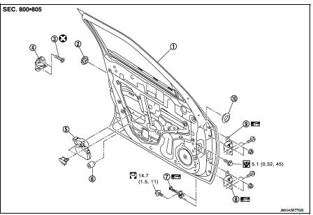
1. Front door panel
2. Grommet
3. TORX bolt
4. Door striker
5. Door pad
6. Bumper rubber
7. Door check link
8. Door hinge (lower)
9. Door hinge (upper)
10. Grommet
 : Do not reuse
 : N·m (kg-m, in-lb)
 : N·m (kg-m, ft-lb)
 : Body grease
Door assembly
DOOR ASSEMBLY : Removal and Installation
CAUTION:
• Perform work with 2 workers, because of its heavy weight.
• When removing and installing front door assembly, support door with a jack and shop cloth to protect door and body.
REMOVAL
1. Disconnect front door harness connector.
2. Remove mounting bolt of door check link on the vehicle.
3. Remove door hinge mounting bolts (door side), and then remove door assembly.
INSTALLATION
Note the following items, and install in the reverse order of removal.
CAUTION:
• Apply anticorrosive agent onto the mounting surface.
• Check front door open/close, lock/unlock operation after installation.
• Check door hinge rotating part for poor lubrication. If necessary, apply body grease.
• After installation, perform the fitting adjustment. Refer to DLK-570, "DOOR ASSEMBLY : Adjustment".
• After installation, apply touch-up paint (the body color) onto the head of door hinge mounting nuts.
DOOR ASSEMBLY : Adjustment
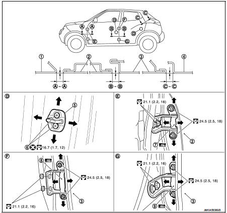
1. Front fender
2. Front door
3. Rear door
4. Body side outer
5. Door striker
6. TORX bolt
7. Front door hinge
8. Rear door hinge (upper)
9. Rear door hinge (lower)
 : Do not reuse
 : N·m (kg-m, ft-lb)
 : Body grease
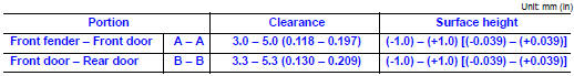
Check the clearance and surface height between front door and each part by visually and touching.
If the clearance and the surface height are out of specification, adjust them according to the procedures shown below.
FITTING ADJUSTMENT PROCEDURE
1. Remove front fender. Refer to DLK-566, "Removal and Installation".
2. Loosen door hinge mounting nuts on door side.
3. Adjust the surface height of front door according to the fitting standard dimension.
4. Temporarily tighten door hinge mounting nuts on door side.
5. Loosen door hinge mounting bolts on body side.
6. Raise front door at rear end to adjust clearance of the front door according to the fitting standard dimension.
7. After adjustment tighten bolts and nuts to the specified torque.
CAUTION:
• After installation, apply touch-up paint (the body color) onto the head of
hinge mounting bolts
and nuts.
• Check door hinge rotating part for poor lubrication. If necessary, apply body grease.
8. Install front fender. Refer to refer to DLK-566, "Removal and Installation".
DOOR STRIKER ADJUSTMENT
Adjust door striker so that it becomes parallel with door lock insertion direction.
Door striker
DOOR STRIKER : Removal and Installation
REMOVAL
Remove TORX bolts, and then remove door striker.
INSTALLATION
Note the following items, and install in the reverse order of removal.
CAUTION:
• Check front door open/close, lock/unlock operation after installation.
• After installation, be sure to perform the fitting adjustment. Refer to DLK-570, "DOOR ASSEMBLY : Adjustment".
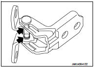
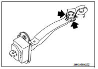
Door hinge
DOOR HINGE : Removal and Installation
REMOVAL
CAUTION:
• Perform work with 2 workers, because of its heavy weight.
• When removing and installing front door assembly, support door with a jack and shop cloth to protect door and body.
1. Remove front fender. Refer to DLK-566, "Removal and Installation".
2. Remove front door assembly. Refer to DLK-568, "DOOR ASSEMBLY : Removal and Installation".
3. Remove front door hinge mounting bolts (body side), and then remove front door hinge.
INSTALLATION
Note the following items, and install in the reverse order of removal.
CAUTION:
• Apply anticorrosive agent onto the mounting surface.
• Check front door open/close, lock/unlock operation after installation.
• After installation, perform the fitting adjustment. Refer to DLK-570, "DOOR ASSEMBLY : Adjustment".
• After installation, apply touch-up paint (the body color) onto the head of door hinge mounting nuts.
• Check door hinge rotating part for poor lubrication. If necessary, apply body grease.
 : Grease up point
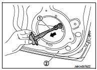
Door check link
DOOR CHECK LINK : Removal and Installation
REMOVAL
1. Fully close the front door window.
2. Remove front door finisher. Refer to INT-13, "Removal and Installation".
3. Disconnect harness connector of front door speaker.
4. Remove mounting bolts of front door speaker, and then remove front door speaker.
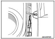
5. Remove mounting bolt of door check link on the vehicle.
6. Remove mounting bolts of door check link on door panel.
7. Take door check link (1) out from the hole of door panel
INSTALLATION
Note the following item, and install in the reverse order of removal.
CAUTION:
• Check front door open/close operation after installation.
• Check door check link rotating part for poor lubrication. If necessary, apply grease.
 : Grease up point
 Front fender
Exploded View
1. Front fender assembly
2. Front fender stiffener
: Vehicle front
Removal and Installation
REMOVAL
1. Remove front fillet molding. Refer to EXT-26, "FRONT FILLET MOLDING : ...
 Rear door
Exploded View
1. Rear door panel
2. TORX bolt
3. Door striker
4. Door check link
5. Door hinge (lower)
6. Door hinge (upper)
: Do not reuse
: N·m (kg-m, in-lb)
: N·m (kg-m, ft-lb)
: ...
Other materials:
On Board Diagnostic (OBD) System of Engine and CVT
The ECM has an on board diagnostic system. It will light up the malfunction
indicator (MI) to warn the driver of
a malfunction causing emission deterioration.
CAUTION:
• Be sure to turn the ignition switch OFF and disconnect the negative battery
cable before any repair
or inspection work ...
Shift lock system
Component Function Check
1.CHECK SHIFT LOCK OPERATION (PART 1)
1. Turn ignition switch ON.
2. Shift the selector lever to “P” position.
3. Attempt to shift the selector lever to any other than position with the brake
pedal released.
Can the selector lever be shifted to any other positio ...
Removal and installation
HORN
Exploded View
WITHOUT VEHICLE SECURITY SYSTEM
1. Horn high
2. Horn low
3. Horn bracket
WITH VEHICLE SECURITY SYSTEM
1. Horn low
2. Horn bracket
Removal and Installation
REMOVAL
Without Vehicle Security System
1. Remove the front center grille and front side grille (LH/RH). Re ...
