Nissan Juke Service and Repair Manual : Front fender
Exploded View
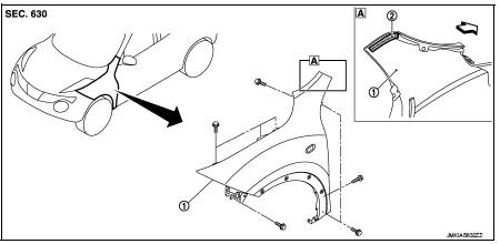
1. Front fender assembly 2. Front fender stiffener
 : Vehicle front
Removal and Installation
REMOVAL
1. Remove front fillet molding. Refer to EXT-26, "FRONT FILLET MOLDING : Removal and Installation".
2. Remove front bumper fascia assembly. Refer to EXT-13, "Removal and Installation".
3. Remove sill cover. Refer to EXT-23, "Removal and Installation".
4. Remove fender protector. Refer to EXT-22, "Removal and Installation".
5. Remove front fender cover. Refer to EXT-20, "Exploded View".
6. Remove front combination lamp. Refer to EXL-91, "Removal and Installation".
7. Remove side turn signal lamp. Refer to EXL-98, "Removal and Installation".
8. Remove mounting bolts of front fender assembly.
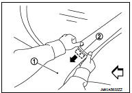
9. Remove front fender stiffener (2) from the vehicle body while carefully pulling upper portion of front fender (1) toward vehicle outside.
 : Vehicle front
10. Remove front fender assembly.
CAUTION:
An viscous urethane foam is installed on the back surface of front fender. When
removing the
front fender, be careful to not deform the front fender while performing the
procedure and removing
the viscous urethane foam a little at a time.
INSTALLATION
Note the following items, and install in the reverse order of removal.
CAUTION:
• After installation, apply the touch-up paint (the body color) onto the head of
front fender mounting
bolts.
• After installation, adjust the following part.
- Hood assembly: Refer to DLK-556, "HOOD ASSEMBLY : Adjustment".
- Front door: Refer to DLK-570, "DOOR ASSEMBLY : Adjustment".
 Radiator core supporT
HR16DE
HR16DE : Exploded View
1. Radiator core support upper
2. Air guide RH (MT models)
3. Radiator core support lower
4. Air guide LH
5. Air guide (upper)
6. Air guide LH (CVT models)
...
 Front door
Exploded View
1. Front door panel
2. Grommet
3. TORX bolt
4. Door striker
5. Door pad
6. Bumper rubber
7. Door check link
8. Door hinge (lower)
9. Door hinge (upper)
10. Grommet
: D ...
Other materials:
Front washer nozzle and tube
Exploded View
LHD models
1. Front washer nozzle LH
2. Front washer nozzle RH
3. Cowl top cover
4. Front washer tube (tank side)
5. Front washer tube RH
6. Front washer tube LH
: Vehicle front
Hydraulic Layout
1. Front washer nozzle
2. Check valve
3. Front washer
4. Washer tank ...
Tire Pressure Monitoring System (TPMS)
Your Nissan Leaf is equipped with a sophisticated Tire Pressure Monitoring System (TPMS) that continuously tracks the inflation pressure of all four tires. When the dedicated low tire pressure warning light illuminates on the instrument cluster, accompanied by the "Tire Pressure Low - Add Air" notif ...
ECU diagnosis information
EPS control unit
Reference Value
VALUES ON THE DIAGNOSIS TOOL
CAUTION:
The output signal indicates the EPS control unit calculation data. The normal
values will be displayed
even in the event that the output circuit (harness) is open.
*1: Almost in accordance with the value of “MOTOR SIG ...
