Nissan Juke Service and Repair Manual : EGR valve
Exploded View
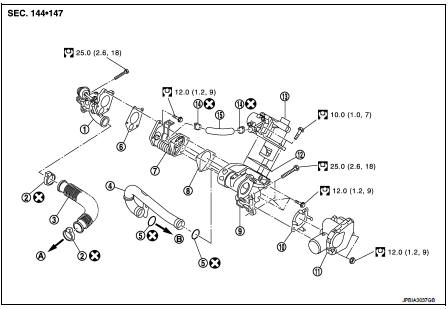
1. EGR valve assembly
2. Clamp
3. EGR tube
4. Air inlet tube
5. O-ring
6. Gasket
7. EGR cooler
8. Gasket
9. EGR volume control valve housing
10. Gasket
11. Electric throttle control actuator
12. Gasket
13. EGR volume control valve
14. Clamp
15. Cooling hose
A. To exhaust manifold B. To intake manifold
 : N·m (kg-m, ft-lb)
 : Always replace after every
disassembly.
Removal and Installation
REMOVAL
1. Drain engine coolant. Refer to CO-62, "Draining".
2. Remove air cleaner case. Refer to EM-280, "Exploded View".
3. Remove cowl top extension. Refer to EXT-20, "Exploded View".
4. Remove turbocharger air inlet pipe. Refer to EM-280, "Exploded View".
5. Remove air inlet tube assembly and air inlet tube. Refer to EM-281, "Exploded View".
6. Remove electric throttle control actuator.
7. Disconnect EGR solenoid valve connector.
8. Remove cooling hose.
9. Remove EGR volume control valve housing mounting bolts.
10. Remove EGR assembly.
INSTALLATION
• Install in the reverse order of removal.
 Charge air cooler
Exploded View
1. Air inlet hose
2. Clamp
3. Air inlet tube
4. Air inlet hose
5. Charge air cooler
6. Air inlet hose
7. Air inlet tube
8. Turbocharger
9. Air inlet tube assembly
A. 1 ...
 Turbocharger
Exploded View
1. Exhaust manifold
2. Turbocharger
3. Gasket
4. Turbocharger outlet duct
5. Oil outlet hose
6. Clamp
7. Oil return pipe
8. Gasket
9. Washer
10. Oil supply tube
11. O ...
Other materials:
Fuel injector and fuel tube
Exploded View
1. Stud bolt
2. O-ring (green)
3. Fuel injector (front)
4. Clip
5. Fuel injector (rear)
6. O-ring (black)
7. Fuel tube protector
8. Fuel tube
9. Fuel feed hose
10. Quick connector cap
A. To centralized under-floor piping
: Always replace after every
disassembly.
...
Periodic maintenance
GEAR OIL
Inspection
OIL LEAKAGE
Make sure that gear oil is not leaking from transaxle or around it.
OIL LEVEL
1. Remove filler plug (1) and gasket from transaxle case.
2. Check the oil level from filler plug mounting hole as shown in the
figure.
CAUTION:
Never start engine while checkin ...
Windshield wiper blades
Cleaning
If your windshield fails to clear properly after utilizing the washer system, or if you notice the wiper blades "chattering" and skipping across the glass during operation, this is often a sign that road film, wax, or other environmental contaminants have accumulated on the rubber blad ...
