Nissan Juke Service and Repair Manual : Charge air cooler
Exploded View
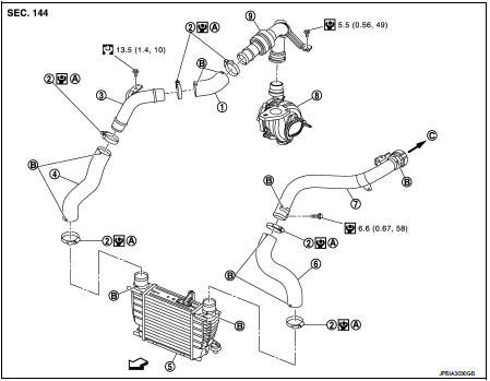
1. Air inlet hose
2. Clamp
3. Air inlet tube
4. Air inlet hose
5. Charge air cooler
6. Air inlet hose
7. Air inlet tube
8. Turbocharger
9. Air inlet tube assembly
A. 1st step: 5.0 N·m (0.51 kg-m, 44 ft-lb)
2nd step: 7.0 N·m (0.71 kg-m, 62 ftlb)
B. Paint mark
C. To electric throttle control actuator
 : Vehicle front
 : N·m (kg-m, ft-lb)
 : N·m (kg-m, in-lb)
Removal and Installation
REMOVAL
1. Remove front bumper. Refer to EXT-12, "Exploded View".
2. Remove air guide (RH).
3. Remove air inlet hose between air inlet tube and charge air cooler.
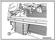
4. Remove charge air cooler (1).
CAUTION:
• Avoid interference between the charge air cooler and radiator.
• When removing charge air cooler, close opening on turbo charger and intake manifold with shop cloth or other suitable material
.
INSTALLATION
Install in the reverse order of removal paying attention to the following
points:
• Apply a neutral detergent (fluid) to the joint between hoses and pipes (oil is
not permissible).
• Pay attention to identification mark and direction.
• When installing air inlet hoses and tubes. Refer to EM-281, "Removal and Installation".
Inspection
INSPECTION AFTER REMOVAL
1. Check that the charge air cooler is not full of oil. In that case, clean it with cleaning agent and then let it dry.
2. Check air passages of charge air cooler core and fins for clogging, leaks or deformation. Clean or replace charge air cooler in necessary.
• Be careful not to deform core fins.
• For cleaning procedure of charge air cooler core, refer to CO-59, "Inspection".
 Air cleaner and air duct
Exploded View
1. Turbocharger air inlet pipe
2. Clamp
3. Air duct (suction)
4. Air mass flow sensor
5. O-ring
6. Air duct (inlet)
7. Grommet
8. Air cleaner case
9. Air cleaner filter
...
 EGR valve
Exploded View
1. EGR valve assembly
2. Clamp
3. EGR tube
4. Air inlet tube
5. O-ring
6. Gasket
7. EGR cooler
8. Gasket
9. EGR volume control valve housing
10. Gasket
11. Electric t ...
Other materials:
Intelligent Key operating range
The Intelligent Key functions can only be used when the Intelligent Key is within
the specified operating range from the request switch 1 .
When the Intelligent Key battery is discharged or strong radio waves are present
near the operating location, the Intelligent Key system’s operating ra ...
Precaution Necessary for Steering Wheel Rotation
after Battery Disconnect
NOTE:
• Before removing and installing any control units, first turn the push-button
ignition switch to the LOCK position,
then disconnect both battery cables.
• After finishing work, confirm that all control unit connectors are connected
properly, then re-connect both
battery cables.
â ...
Off-road recovery
If the right side or left side wheels leave the road surface, maintain control
of the vehicle by following the procedure below. Please note that this procedure
is only a general guide. The vehicle must be driven as appropriate based on the
conditions of the vehicle, road and traffic.
1. Remai ...
