Nissan Juke Service and Repair Manual : Differential side oil seal
Exploded View
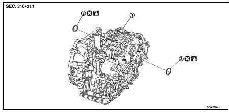
1. Transaxle assembly 2. Differential side oil seal (left side) 3. Differential side oil seal (right side)
 : Always replace after every
disassembly.
 : Genuine NISSAN CVT Fluid NS-2
Removal and Installation
REMOVAL
NOTE
:
Cap or plug openings to prevent fluid from spilling.
1. Remove the left front drive shaft. Refer to FAX-22, "LEFT SIDE : Removal and Installation".
2. Remove the transfer assembly. Refer to DLN-93, "Removal and Installation".
3. Use oil seal remover or a similar means and remove the differential side oil seal.
CAUTION:
When removing the differential side oil seal, be careful not to scratch the oil
seal mounting surfaces
of the transaxle case and converter housing.
INSTALLATION
Note the following, and install in the reverse order of removal.
CAUTION:
ŌĆó Never reuse differential side oil seal.
ŌĆó Apply Genuine NISSAN CVT Fluid NS-2 to the differential side oil seal lip and around the oil seal.
ŌĆó When inserting the drive shaft, be sure to use a protector (SST: KV38107900). Refer to FAX-22, "LEFT SIDE : Removal and Installation".
Use a drift (commercial service tool) and drive the differential side oil seal in until the amount of oil seal projection from the case edge matches dimensions (C) and (D).
CAUTION:
Be careful not to scratch the lip of the differential side oil seal
when press-fitting it.
A : Differential side oil seal (left side) B : Differential side oil seal (right side)
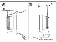
Dimension ŌĆ£CŌĆØ :Height difference from case end surface is within 1.8 ┬▒ 0.5 mm (0.071 ┬▒ 0.020 in).
Dimension ŌĆ£DŌĆØ :Height difference from case end surface is within 1.0 ┬▒ 0.5 mm (0.039 ┬▒ 0.020 in).
NOTE
:
The reference is the pull-in direction of the differential side oil seal.
Inspection
After completing installation, check for CVT fluid leakage and CVT fluid level. Refer to TM-184, "Inspection".
 Secondary speed sensor
Exploded View
1. Transaxle assembly
2. Secondary speed sensor
3. O-ring
: Always replace after every
disassembly.
: N┬Ęm (kg-m, in-lb)
: Genuine NISSAN CVT Fluid NS-2
Removal and Installa ...
 Oil pump fitting bolt
Description
Replace the oil pump fitting bolt and the O-ring if oil leakage or exudes
from the oil pump fitting bol
Exploded View
1. Oil pump fitting bolt
2. O-ring
3. Transaxle assembly
: ...
Other materials:
C1120, C1122, C1124, C1126 ABS in valve system
DTC Logic
DTC DETECTION LOGIC
DTC CONFIRMATION PROCEDURE
1.PRECONDITIONING
If ŌĆ£DTC CONFIRMATION PROCEDUREŌĆØ has been previously conducted, always turn
ignition switch OFF and
wait at least 10 seconds before conducting the next test.
>> GO TO 2.
2.CHECK DTC DETECTION
With CON ...
P1745 line pressure control
Description
The line pressure solenoid valve regulates the oil pump discharge pressure to
suit the driving condition in
response to a signal sent from the TCM.
DTC Logic
DTC DETECTION LOGIC
DTC CONFIRMATION PROCEDURE
NOTE:
If ŌĆ£DTC CONFIRMATION PROCEDUREŌĆØ has been previously performed, ...
Front fog lamp circuit
Component Function Check
1.CHECK FRONT FOG LAMP OPERATION
CONSULT-III ACTIVE TEST
1. Select ŌĆ£EXTERNAL LAMPSŌĆØ of IPDM E/R active test item.
2. With operating the test items, check that the front fog lamp is turned ON.
Fog : Front fog lamp ON
Off : Front fog lamp OFF
Is the measurement norm ...
