Nissan Juke Service and Repair Manual : Diagnosis system (BCM) (without intelligent key system)
Common item
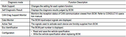
COMMON ITEM : CONSULT-III Function (BCM - COMMON ITEM)
APPLICATION ITEM
CONSULT-III performs the following functions via CAN communication with BCM.
SYSTEM APPLICATION
BCM can perform the following functions for each system.
NOTE
:
It can perform the diagnosis modes except the following for all sub system
selection items.
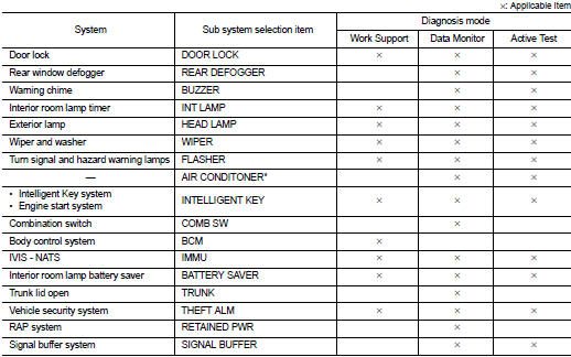
*: This item is not used.
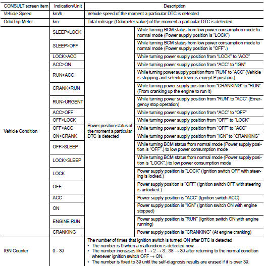
FREEZE FRAME DATA (FFD)
The BCM records the following vehicle condition at the time a particular DTC is detected, and displays on CONSULT-III.
INT lamp
INT LAMP : CONSULT-III Function (BCM - INT LAMP
)
WORK SUPPORT
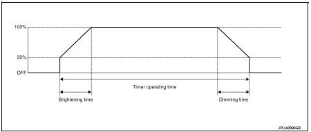
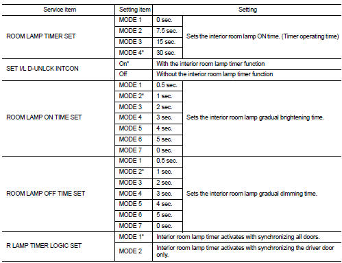
*: Factory setting
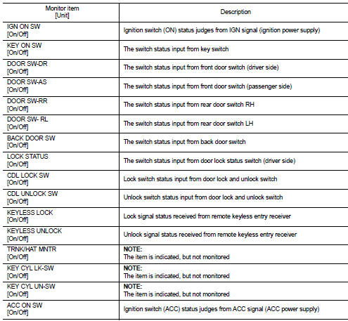
DATA MONITOR
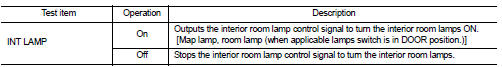
ACTIVE TEST
Battery saver
BATTERY SAVER : CONSULT-III Function (BCM - BATTERY SAVER)
WORK SUPPORT
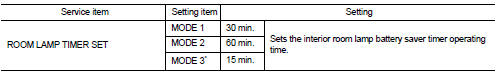
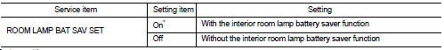
*:Factory setting
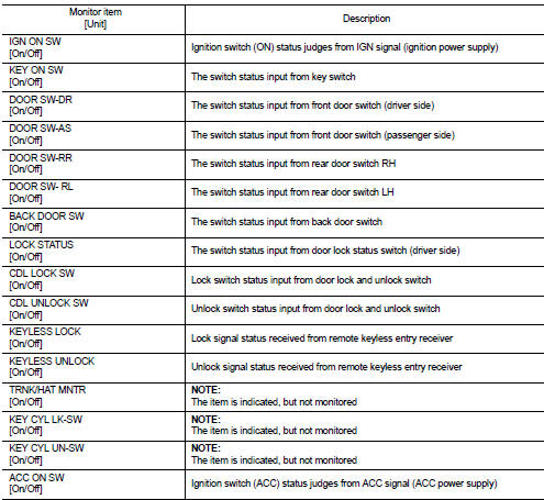
DATA MONITOR
ACTIVE TEST
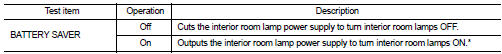
*: Each lamp switch is in ON position.
 Diagnosis system (BCM) (with intelligent key system)
Common item
COMMON ITEM : CONSULT-III Function (BCM - COMMON ITEM)
APPLICATION ITEM
CONSULT-III performs the following functions via CAN communication with BCM.
SYSTEM APPLICATION
BCM can perfo ...
 Ecu diagnosis information
BCM
With intelligent key
WITH INTELLIGENT KEY : List of ECU Reference
Without intelligent key
WITHOUT INTELLIGENT KEY : List of ECU Reference
...
Other materials:
Automatic climate control
(models without Navigation System)
fan speed control dial
intake air control
button
front defroster button
Climate Ctrl. display (dedicated monochromatic status screen for reading target t ...
General maintenance
General Maintenance
General maintenance includes those items which should be checked during the
normal day-to-day operation
of the vehicle. They are essential if the vehicle is to continue operating
properly. The owners can perform
checks and inspections themselves or they can have their NISS ...
Consult-III/GST checking system
Description
• When CONSULT-III/GST is connected with a data link connector
(A) equipped on the vehicle side, it will communicate with the control
unit equipped in the vehicle and then enable various kinds of
diagnostic tests.
1 : Instrument lower panel RH
• Refer to CONSULT-III Software O ...
