Nissan Juke Service and Repair Manual : Diagnosis system (A/C auto AMP.)
Description
Air conditioning system performs self-diagnosis, operation check, function diagnosis, and various settings using diagnosis function of each control unit.
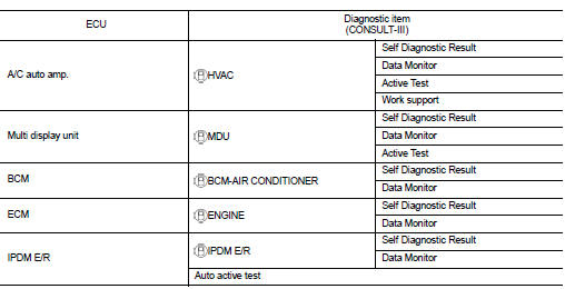
CONSULT-III Function
CONSULT-III performs the following functions via CAN communication with A/C auto amp.
NOTE
:
Diagnosis should be performed with engine running. Door motor operation speeds
become slower and NO
results may be returned even for normal operation if battery voltage drops below
12 V during self-diagnosis.
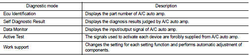
ECU IDENTIFICATION
Part number of A/C auto amp. can be checked.
SELF-DIAGNOSIS RESULTS
Diagnosis result that is judged by A/C auto amp. can be checked. Refer to HAC-39, "DTC Index".
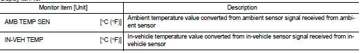
DATA MONITOR
Input/output signal of A/C auto amp. can be checked.
Display item list
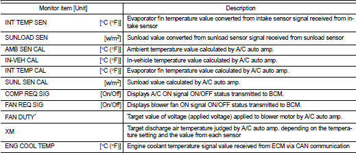
*: “DUTY” is displayed, but voltage is indicated. Or unit is not displayed but unit is (V).
ACTIVE TEST
The signals used to activate each device forcibly supplied from A/C auto amp. operation check of air conditioning system can be performed.

Check each output device
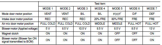
*: Position of mode door motor is set to the status of automatic control that is selected by foot position setting trimmer. Refer to HAC-49, "Foot Position Setting Trimmer".
NOTE
:
Perform the inspection of each output device after starting the engine because
the compressor is operated.
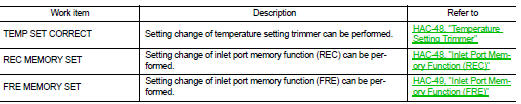
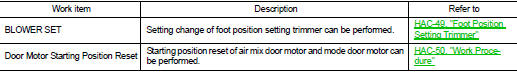
WORK SUPPORT
Setting change of each setting functions and automatic adjustment of components can be performed.
NOTE
:
When the battery cable is disconnected from the negative terminal or when the
battery voltage becomes 10 V
or less, the setting of WORK SUPPORT may be cancelled.
 Operation
Switch Name and Function
OPERATION AND DISPLAY
A/C Display (Display in Multi Display Unit)
• Air conditioning system operation status is indicated on display in multi
display unit. Indication ...
 Diagnosis system (BCM) (with intelligent key system)
Common item : consult-III Function (BCM - common item)
APPLICATION ITEM
CONSULT-III performs the following functions via CAN communication with BCM.
SYSTEM APPLICATION
BCM can perform the follow ...
Other materials:
P0117, P0118 ECT sensor
DTC Logic
DTC DETECTION LOGIC
DTC CONFIRMATION PROCEDURE
1.PRECONDITIONING
If DTC Confirmation Procedure has been previously conducted, always perform
the following procedure
before conducting the next test.
1. Turn ignition switch OFF and wait at least 10 seconds.
2. Turn ignition swit ...
Additional service when replacing ECM
Description
When replacing ECM, this procedure must be performed.
Work Procedure
1.PRECONDITIONING
• Connect a CONSULT-III
• Connect a battery charger
• Electric load switch is OFF
• Wait for the engine to cool [engine coolant temperature < 60?°C (140?°F) and air
temperature &l ...
MR16DDT : Inspection and Adjustment
INSPECTION
Magnetic Switch Check
• Before starting to check, disconnect the battery cable from the negative
terminal.
• Disconnect “M” terminal of starter motor.
1. Continuity test [between “S” terminal (A) and switch body]
B : “B” terminal
C : “M” terminal
• Replace ...
