Nissan Juke Service and Repair Manual : Diagnosis and repair workflow
Work Flow
OVERALL SEQUENCE
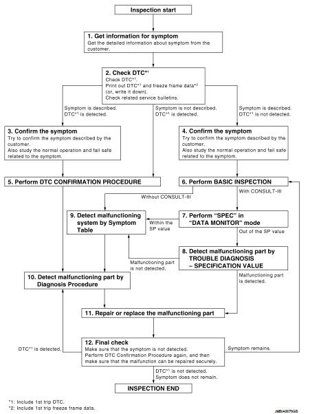
DETAILED FLOW
1.GET INFORMATION FOR SYMPTOM
Get the detailed information from the customer about the symptom (the condition and the environment when the incident/malfunction occurred) using the “Diagnostic Work Sheet”. (Refer to EC-539, "Diagnostic Work Sheet".) >> GO TO 2.
2.CHECK DTC
1. Check DTC.
2. Perform the following procedure if DTC is displayed.
- Record DTC and freeze frame data. (Print them out with CONSULT-III or GST.) - Erase DTC.
- Study the relationship between the cause detected by DTC and the symptom described by the customer.
(Symptom Table is useful. Refer to EC-795, "Symptom Table".) 3. Check related service bulletins for information.
Is any symptom described and is any DTC detected? Symptom is described, DTC is detected>>GO TO 3.
Symptom is described, DTC is not detected>>GO TO 4.
Symptom is not described, DTC is detected>>GO TO 5.
3.CONFIRM THE SYMPTOM
Try to confirm the symptom described by the customer (except MI ON).
Also study the normal operation and fail safe related to the symptom. Refer to EC-800, "Description" and EC- 519, "Fail Safe".
Diagnostic Work Sheet is useful to verify the incident.
Verify relation between the symptom and the condition when the symptom is detected.
>> GO TO 5.
4.CONFIRM THE SYMPTOM
Try to confirm the symptom described by the customer.
Also study the normal operation and fail safe related to the symptom. Refer to EC-800, "Description" and EC- 519, "Fail Safe".
Diagnostic Work Sheet is useful to verify the incident.
Verify relation between the symptom and the condition when the symptom is detected.
>> GO TO 6.
5.PERFORM DTC CONFIRMATION PROCEDURE
Perform DTC CONFIRMATION PROCEDURE for the displayed DTC, and then make sure that DTC is detected again.
If two or more DTCs are detected, refer to EC-521, "DTC Inspection Priority Chart" and determine trouble diagnosis order.
NOTE
:
• Freeze frame data is useful if the DTC is not detected.
• Perform Component Function Check if DTC CONFIRMATION PROCEDURE is not included on Service Manual. This simplified check procedure is an effective alternative though DTC cannot be detected during this check.
If the result of Component Function Check is NG, it is the same as the detection of DTC by DTC CONFIRMATION PROCEDURE.
Is DTC detected? YES >> GO TO 10.
NO >> Check according to GI-42, "Intermittent Incident".
6.PERFORM BASIC INSPECTION
Perform EC-547, "Work Procedure".
Do you have CONSULT-III?
YES >> GO TO 7.
NO >> GO TO 9.
7.PERFORM “SPEC” IN DATA MONITOR MODE
 With CONSULT-III
Make sure that “MAS A/F SE-B1”, “B/FUEL SCHDL” and “A/F ALPHA-B1” are within the SP value in “SPEC” of “DATA MONITOR” mode with CONSULT-III. Refer to EC-558, "Component Function Check".
Is the measurement value within the SP value? YES >> GO TO 9.
NO >> GO TO 8.
8.DETECT MALFUNCTIONING PART BY TROUBLE DIAGNOSIS - SPECIFICATION VALUE
Detect malfunctioning part according to EC-559, "Diagnosis Procedure".
Is malfunctioning part detected? YES >> GO TO 11.
NO >> GO TO 9.
9.DETECT MALFUNCTIONING SYSTEM BY SYMPTOM TABLE
Detect malfunctioning system according to EC-795, "Symptom Table" based on the confirmed symptom in step 4, and determine the trouble diagnosis order based on possible causes and symptom.
>> GO TO 10.
10.DETECT MALFUNCTIONING PART BY DIAGNOSIS PROCEDURE
Inspect according to Diagnosis Procedure of the system.
NOTE
:
The Diagnosis Procedure in EC section described based on open circuit
inspection. A short circuit inspection
is also required for the circuit check in the Diagnosis Procedure. For details,
refer to GI-44, "Circuit Inspection".
Is malfunctioning part detected? YES >> GO TO 11.
NO >> Monitor input data from related sensors or check the voltage of related ECM terminals using CONSULT- III. Refer to EC-508, "Reference Value".
11.REPAIR OR REPLACE THE MALFUNCTIONING PART
1. Repair or replace the malfunctioning part.
2. Reconnect parts or connectors disconnected during Diagnosis Procedure again after repair and replacement.
3. Check DTC. If DTC is displayed, erase it.
>> GO TO 12.
12.FINAL CHECK
When DTC was detected in step 2, perform DTC CONFIRMATION PROCEDURE or Component Function Check again, and then make sure that the malfunction have been repaired securely.
When symptom was described from the customer, refer to confirmed symptom in step 3 or 4, and make sure that the symptom is not detected.
Is DTC detected and does symptom remain? YES-1 >> DTC is detected: GO TO 10.
YES-2 >> Symptom remains: GO TO 6.
NO >> Before returning the vehicle to the customer, make sure to erase unnecessary DTC in ECM. If the completion of SRT is needed, drive vehicle under the specific “DRIVING PATTERN” in EC-554, "SRT Set Driving Pattern".
Diagnostic Work Sheet
DESCRIPTION
There are many operating conditions that lead to the malfunction of engine components. A good grasp of such conditions can make troubleshooting faster and more accurate.
In general, each customer feels differently about an incident. It is important to fully understand the symptoms or conditions for a customer complaint.
Utilize a diagnostic worksheet like the WORKSHEET SAMPLE below in order to organize all the information for troubleshooting.
Some conditions may cause the MI to come on steady or blink and DTC to be detected. Examples: Vehicle ran out of fuel, which caused the engine to misfire.
WORKSHEET SAMPLE
 Basic inspection
...
 Additional service when replacing ECM
Description
When replacing ECM, this procedure must be performed.
Work Procedure
1.PERFORM INITIALIZATION OF NATS SYSTEM AND REGISTRATION OF ALL NATS
IGNITION KEY IDS
Refer to SEC-50, "BCM ...
Other materials:
Steering Assist limitations
WARNING
In the following situations, the front-facing camera may fail to identify lane markers accurately or misinterpret road features, which may result in the Steering Assist system failing to operate as intended:
When navigating roads with confusing, ...
Blower fan on signal
Component Function Check
1.CHECK BLOWER FAN ON SIGNAL
With CONSULT-III
1. Turn ignition switch ON.
2. Select “AIR CONDITIONER” of “BCM” using CONSULT-III.
3. Select “FAN ON SIG” in “DATA MONITOR” mode, and check status under the
following condition.
Is the inspection result ...
U1000 can comm circuit
Description
CAN (Controller Area Network) is a serial communication line for real time
applications. It is an on-vehicle multiplex
communication line with high data communication speed and excellent error
detection ability. Modern
vehicle is equipped with many electronic control unit, and eac ...
