Nissan Juke Service and Repair Manual : C1109 power and ground system
DTC Logic
DTC DETECTION LOGIC
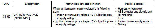
DTC CONFIRMATION PROCEDURE
1.PRECONDITIONING
If ŌĆ£DTC CONFIRMATION PROCEDUREŌĆØ has been previously conducted, always turn ignition switch OFF and wait at least 10 seconds before conducting the next test.
>> GO TO 2.
2.CHECK DTC DETECTION
 With CONSULT-III.
1. Turn the ignition switch OFF to ON.
2. Perform self-diagnosis for ŌĆ£ABSŌĆØ Is DTC ŌĆ£C1109ŌĆØ detected? YES >> Proceed to BRC-160, "Diagnosis Procedure".
NO >> INSPECTION END
Diagnosis Procedure
1.CHECK CONNECTOR
1. Turn the ignition switch OFF.
2. Check ABS actuator and electric unit (control unit) harness connector for disconnection or looseness.
Is the inspection result normal? YES >> GO TO 3.
NO >> Repair or replace error-detected parts, securely lock the connector, and GO TO 2.
2.PERFORM SELF-DIAGNOSIS
Perform self-diagnosis for ŌĆ£ABSŌĆØ again.
Is DTC ŌĆ£C1109ŌĆØ detected? YES >> GO TO 3.
NO >> INSPECTION END
3.CHECK ABS ACTUATOR AND ELECTRIC UNIT (CONTROL UNIT) IGNITION POWER SUPPLY
1. Turn the ignition switch OFF.
2. Disconnect ABS actuator and electric unit (control unit) harness connector.
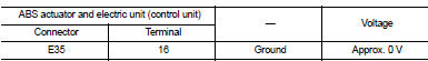
3. Check voltage between ABS actuator and electric unit (control unit) harness connector and ground.
4. Turn the ignition switch ON.
CAUTION:
Never start engine.
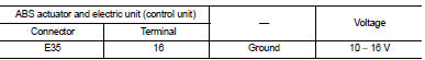
5. Check voltage between ABS actuator and electric unit (control unit) harness connector and ground.
Is the inspection result normal? YES >> GO TO 5.
NO >> GO TO 4.
4.CHECK ABS ACTUATOR AND ELECTRIC UNIT (CONTROL UNIT) IGNITION POWER SUPPLY CIRCUIT
1. Turn the ignition switch OFF.
2. Check 10 A fuse (#57).
3. Disconnect IPDM E/R harness connector.
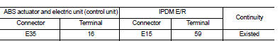
4. Check continuity between ABS actuator and electric unit (control unit) harness connector and IPDM E/R harness connector.
5. Check for continuity between ABS actuator and electric unit (control unit) harness connector and the ground.
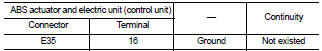
Is the inspection result normal? YES >> Perform trouble diagnosis for ignition power supply. Refer to PG-15, "Wiring Diagram - IGNITION POWER SUPPLY -".
NO >> Repair or replace error-detected parts.
5.CHECK ABS ACTUATOR AND ELECTRIC UNIT (CONTROL UNIT) GROUND CIRCUIT
1. Turn the ignition switch OFF.
2. Check continuity between ABS actuator and electric unit (control unit) harness connector and groun
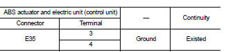
Is the inspection result normal? YES >> GO TO 6.
NO >> Repair or replace error-detected parts.
6.CHECK TERMINAL
ŌĆó Check ABS actuator and electric unit (control unit) pin terminals for damage or loose connection with harness connector.
ŌĆó Check IPDM E/R pin terminals for damage or loose connection with harness connector.
Is the inspection result normal? YES >> Replace ABS actuator and electric unit (control unit). Refer to BRC-233, "Removal and Installation".
NO >> Repair or replace error-detected parts.
 C1105, C1106, C1107, C1108 wheel sensor
DTC Logic
DTC DETECTION LOGIC
DTC CONFIRMATION PROCEDURE
1.PRECONDITIONING
If ŌĆ£DTC CONFIRMATION PROCEDUREŌĆØ has been previously conducted, always turn
ignition switch OFF and
wait at least ...
 C1110, C1170 ABS actuator and electric unit (control unit)
DTC Logic
DTC DETECTION LO
DTC CONFIRMATION PROCEDURE
1.PRECONDITIONING
If ŌĆ£DTC CONFIRMATION PROCEDUREŌĆØ has been previously conducted, always turn
ignition switch OFF and
wait at least 10 ...
Other materials:
Rear window defogger does not operate but both door
mirror defoggers operate
Diagnosis Procedure
1.CHECK REAR WINDOW DEFOGGER
Check rear window defogger.
Refer to DEF-31, "Component Function Check".
Is the inspection result normal?
YES >> GO TO 2.
NO >> Repair or replace the malfunctioning parts.
2.CONFIRM THE OPERATION
Confirm the opera ...
Steering gear and linkage
Exploded View
REMOVAL
LHD Models
1. Steering gear assembly
2. Heat insulator
3. Front suspension member
: Vehicle front
: Always replace after every
disassembly.
: N┬Ęm (kg-m, ft-lb)
: N┬Ęm (kg-m, in-lb)
RHD Models
1. Steering gear assembly
2. Heat insulator
3. Front suspensio ...
Wiring diagram
Engine control system
Wiring Diagram
For connector terminal arrangements, harness layouts, and alphabets in a
(option abbreviation; if not
described in wiring diagram), refer to GI-12, "Connector Information/Explanation
of Option Abbreviation".
...
