Nissan Juke Service and Repair Manual : Wiring diagram
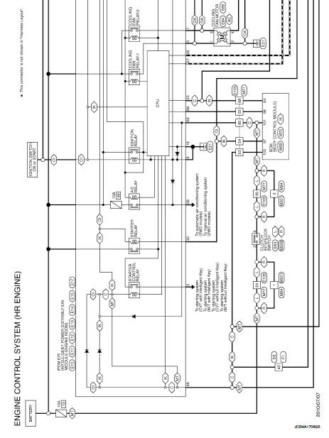
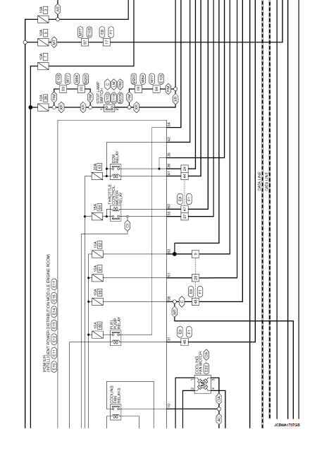
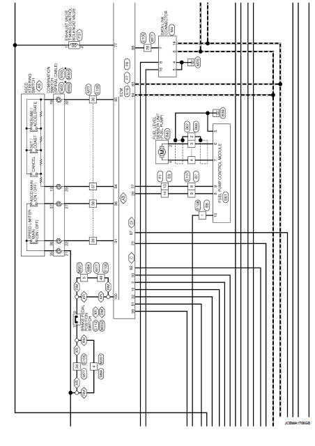
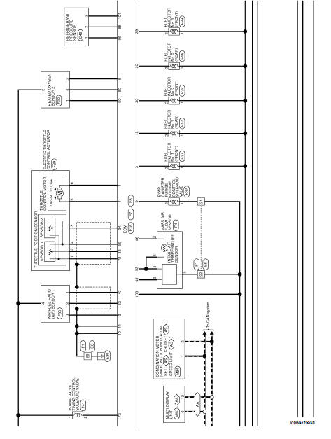
Engine control system
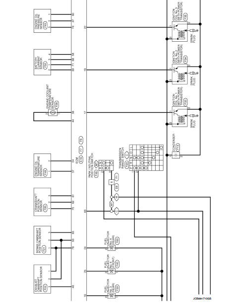
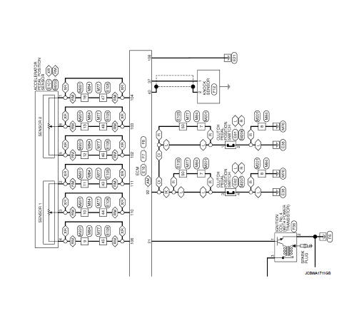
Wiring Diagram
For connector terminal arrangements, harness layouts, and alphabets in a
 (option abbreviation; if not
described in wiring diagram), refer to GI-12, "Connector Information/Explanation
of Option Abbreviation".
 ECU diagnosis information
ECM
Reference Value
VALUES ON THE DIAGNOSIS TOOL
Remarks:
• Specification data are reference values.
• Specification data are output/input values which are detected or supplied by
the ECM a ...
 Basic inspection
...
Other materials:
Antenna
To remove the antenna, hold the bottom of the antenna and turn it counterclockwise.
To install the antenna, turn the antenna clockwise and tighten.
CAUTION
• To avoid damaging or deforming the antenna, be sure to fold down (if so
equipped) or remove the antenna under the following condition ...
Instrument Panel
Vents: Adjustable climate control outlets for personalized cabin airflow.
Meters and gauges: Comprehensive digital driver information display providing real-time vehicle data.
Center multi-function control panel*: Central hub for infotainment, connec ...
General Precautions
• Do not operate the engine for an extended period of time without
proper exhaust ventilation.
Keep the work area well ventilated and free of any inflammable
materials. Special care should be taken when handling any inflammable
or poisonous materials, such as gasoline, refrigerant gas,
etc. ...
